Category Archives: Turret Clock

A new lantern pinion

IMG_4773

This is our first real new part for the clock. This 10 pin lantern pinion is on the escapement arbour and engages with a 120 tooth wheel. The actual arbour and the rusty support in the picture are just temporary.

The bulk of it is made from a single peice of brass. Both sets of holes for the trudles were drilled in one go from one end. This means only one end cap is needed.

The end cap is a separate piece which we intend to solder on, which is how we initially thought the originals were made. Rather than just a washer to cover holes we made a complete end cap, it seemed easier to make that way.  We need to be careful to not get the trundles too hot else they’ll loose their temper. How easy will it be to separate it again in the future to replace a worn pin though? Once the end cap is attached it will be turned down to a perfect match to the body of the pinion.

Lantern pinions

IMG_20141221_133724

In order to faithfully reproduce the original parts we needed to work out how they were actually made. This took a bit of time to work out for the lantern pinions. On initial inspection it wasn’t obvious how they were attached to the arbours, but this turned out to be because they were so dirty and the original fixing was so neat. When we got one cleaned up we finally found a bronze pin in the centre of the pinion. This appeared to have been machined smooth and so blended in really well (hence any dirt, or insufficient light in the workshop, and it was invisible). It shows clearly it the image, but that’s zoomed in, taken with bright flash and I’ve tweaked the colours too so it’s easier to see than looking at the real thing.

However, this pin is beneath the trundles (the pins along the pinions, which engage with the teeth of next wheel in the train) which must have been inserted afterwards, yet the pinions ends aren’t open! This suggested it was made as two separate ends and the trundles sandwiched between them, but then you’d need two pins to hold the ends to the arbour. Only after closer inspection of another lantern pinion on the clock did my Father spot that there were end caps on the pinions. They are basically very well fitting brass washers pushed on to the end to cover the holes containing the trundles (at first we thought they might be soldered on, but apparently they are just pushed on). They are then machined to a perfect fit with a bevelled edge that masks the joint line. On one of the larger pinions there is a small gap where the hole in the washer isn’t a perfect fit around the arbour which gave it away. The result is really neat and serves to emphasise the quality of the original clock.

Escapement

P1080535_zpscfae8fcf.jpg~original

Logically one of the first things we want to get sorted is the going train – no point being able to chime before it can tell the time (although we did already take a slight detour with the arbour supports). To do this we need to replace the following missing parts:

  • the pendulum stand
  • the pendulum
  • the escapement
  • the escapement arbour and lantern pinion

This involves many unknowns. We don’t know the length (and so the period) of the pendulum. We don’t know what kind of escapement it should have. From looking at many similar Smith clocks on the internet (we are yet to find one identical) we are pretty sure it uses a pin wheel escapement. We don’t know how many pins, although most we have seen have 35 pins. We don’t know how many trundles the lantern pinion (opposite end of the arbour to the escape wheel) should have, no clear pictures found on the internet.  However, we do know that the next wheel in the train has 120 teeth, and needs to make 4 full rotations per hour, so we can work backwards to make some sensible suggestions for our unknowns.

120 teeth rotating 4 times per hour makes 480 teeth per hour. With 3600 seconds per hour we need to move one of these teeth every 7.5 seconds. Some measuring of the teeth on the 120 wheel suggest a lantern pinion with 10 trundles. If we assume 35 pins on the escape wheel we have enough information to work out a pendulum length: 7.5 seconds x 10 trundles = 75 seconds per rotation of the escapement arbour. 75 divided by 35 ~= 2.14 seconds for a full swing (back and forth) for the pendulum, which translates into a pendulum length of 1.14m.

Picture is of the escapement of South Mymms Church clock, J Smith & Sons (Derby) ~1892, taken by Harald Mueller.

Rebuilding the cut off arbour supports

IMG_20141202_113448

When the clock was converted to electric drive the back arbour supports were cut down. As the fly was no longer required (in fact it needed to be removed to connect the motors) these post could be cut down to make room for the motor to be mounted.

This seems like a terrible way to do the conversion. The Church Buildings Council of the Church of England provides guidelines on maintaining turret clocks which states, with regard to auto-winders and electric drives, “No parts should be removed from the movement.” and “There should be no cutting or drilling of the clock frame.” It’s likely that this conversion was done a long time ago, long before these rules were written, and was probably just how things were done then.

As they are cast parts welding a piece on top wasn’t going to be easy. Instead the top has been milled perfectly flat and an extra chunk has then been bolted to the top. The sides of the new piece were then milled to match the existing sides. The holes were plugged by hammering in a core of the same steel and the top shaped by hand to match the existing pillars. A hole was then bored to take a new bush (not yet made).

Building a clock stand

IMG_20141204_161400

Working just above floor level wasn’t going to be very comfortable, and you need space underneath the clock to get the barrels out, so a stand was needed. This was made from wood we had on hand, all we needed to buy  to make this was a few extra coach screws. The stand needs to be pretty strong as big cast iron framed turret clocks are heavy (not sure exactly how much this one weighs, we must try and weigh it at some point) and so are the weights and the pendulum . The uprights are 3×3 inch and the the stand is rock solid. As we don’t yet know the pendulum length we made it plenty tall enough and then mounted it on the original wheeled boards I got with the clock. The result was a little too high to work on comfortably so we ended up having to shortening the uprights a little.

Restoring a J Smith & Sons (Derby) turret clock

4695_0

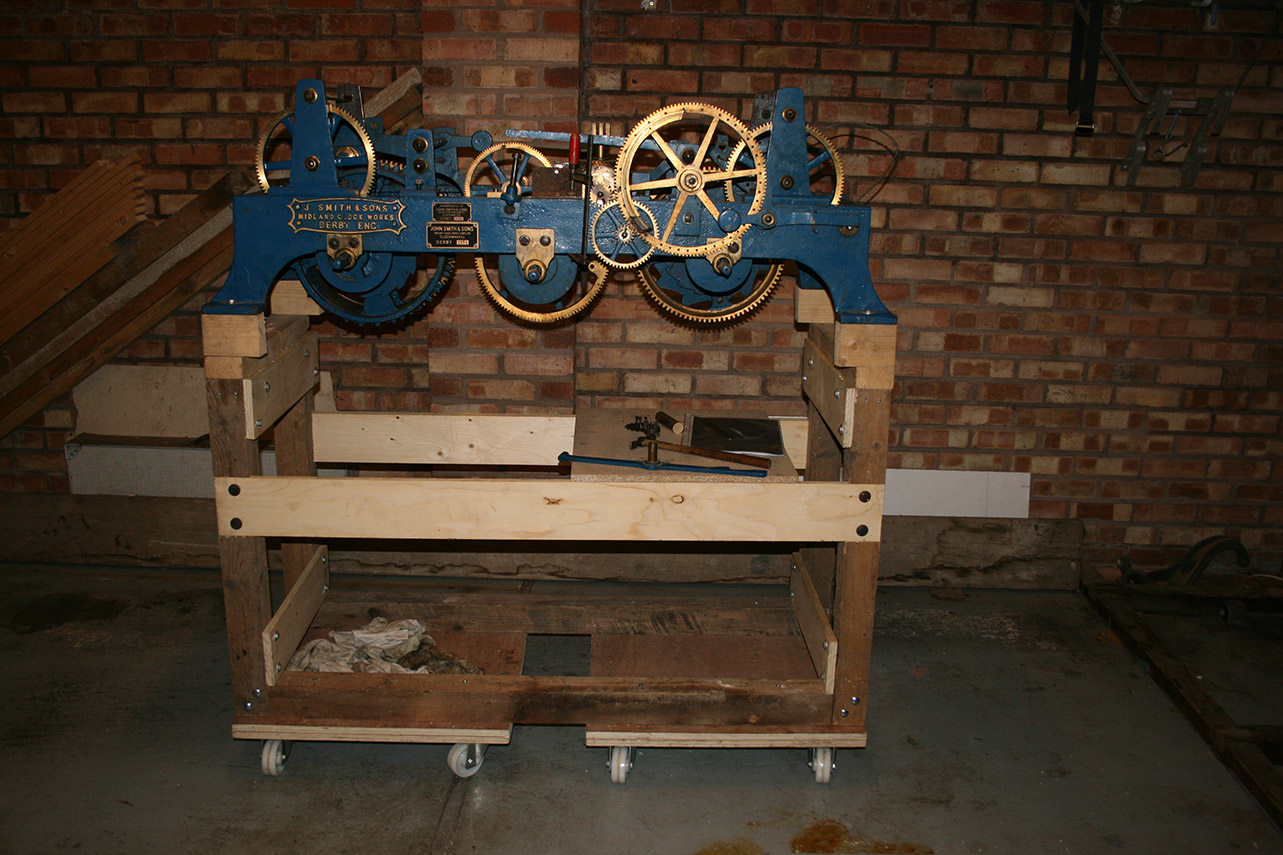
I’ve wanted a turret clock for a long time. I must have gained this interest from my father who is a keen amateur horologist. Although clocks and watches interest me to a reasonable extent, it was a turret clock that I always fancied. It’s probably something about the scale that’s more impressive. After getting to visit the Smith of Derby workshops (through my own work, unrelated to clocks) I was inspired to finally get one. And being a Derbyshire native it had to be a Smith of course, I was also quite keen on the look of their cast iron flat bed clocks from the early 1900s. Problem is there aren’t all that many about for sale and if you’re going to do it properly you want a large three train movement. Three trains means it keeps time, strikes the  hour and chimes. Smaller two train movements seem to come up for sale a bit more often, although I only know of one currently available.

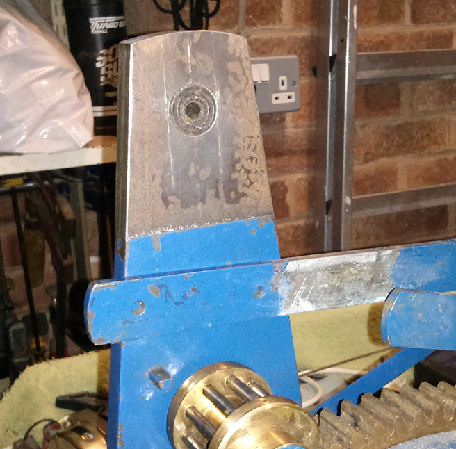
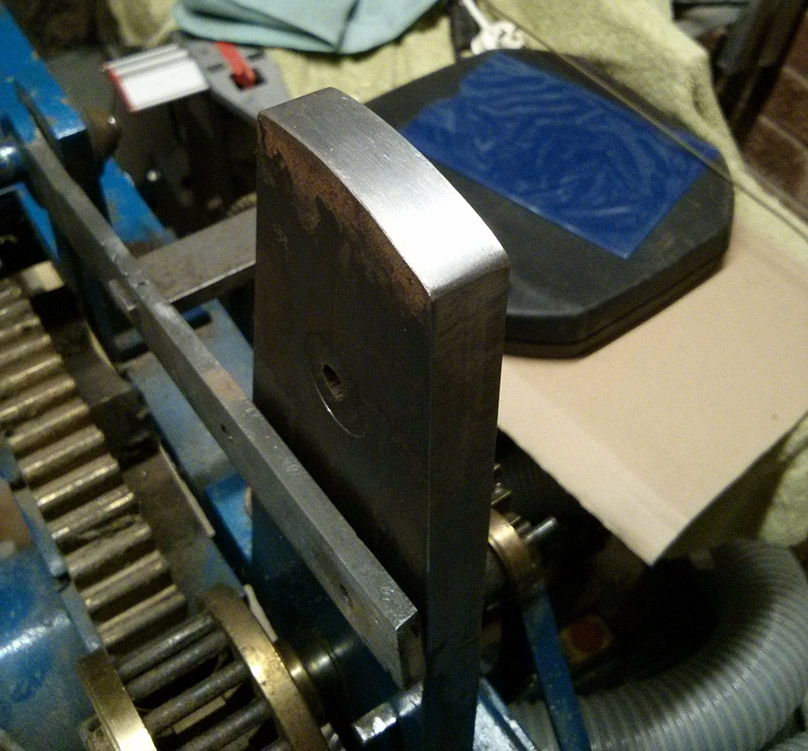
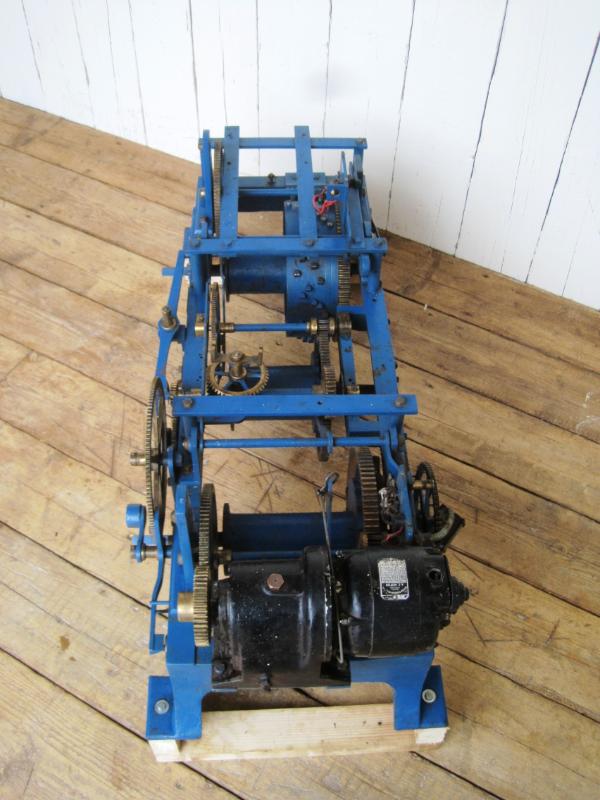
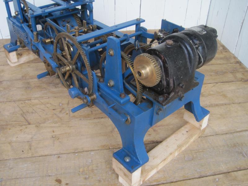
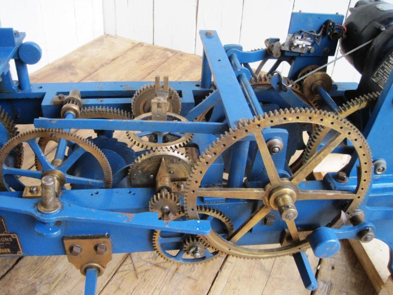
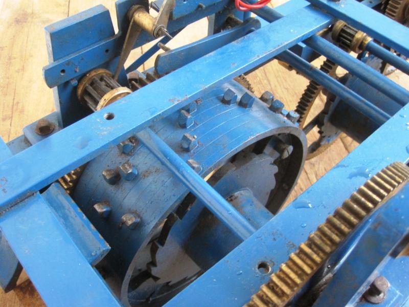
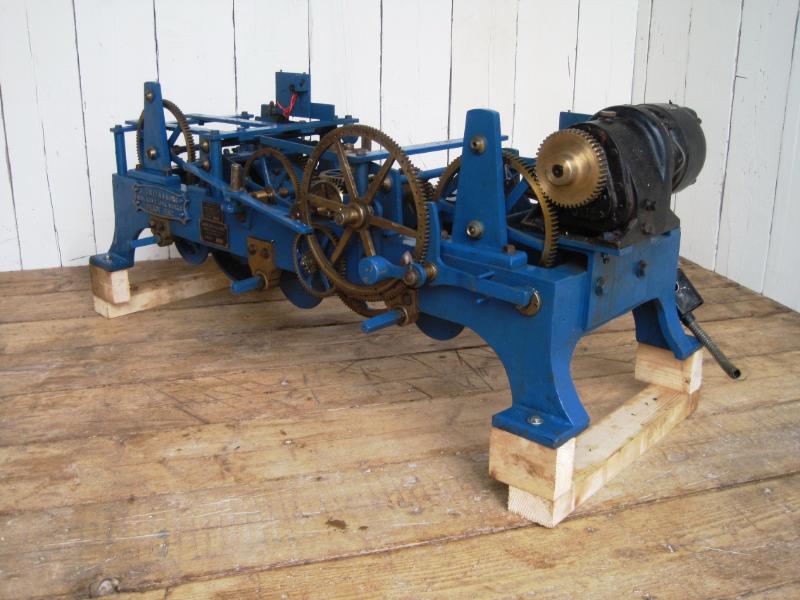
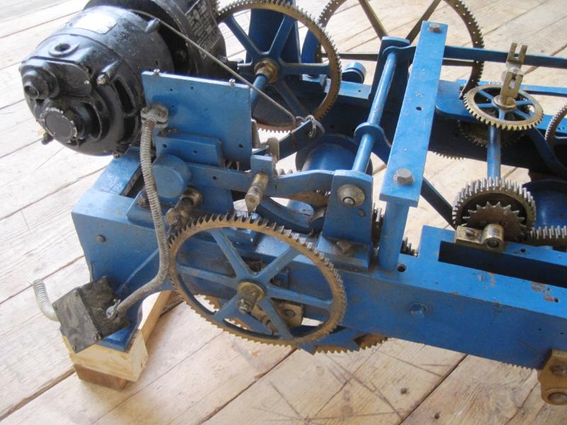
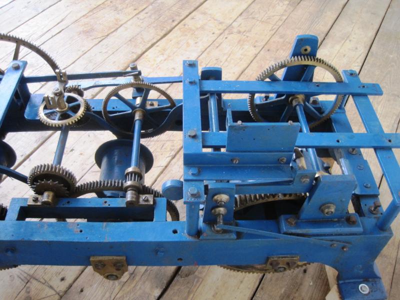
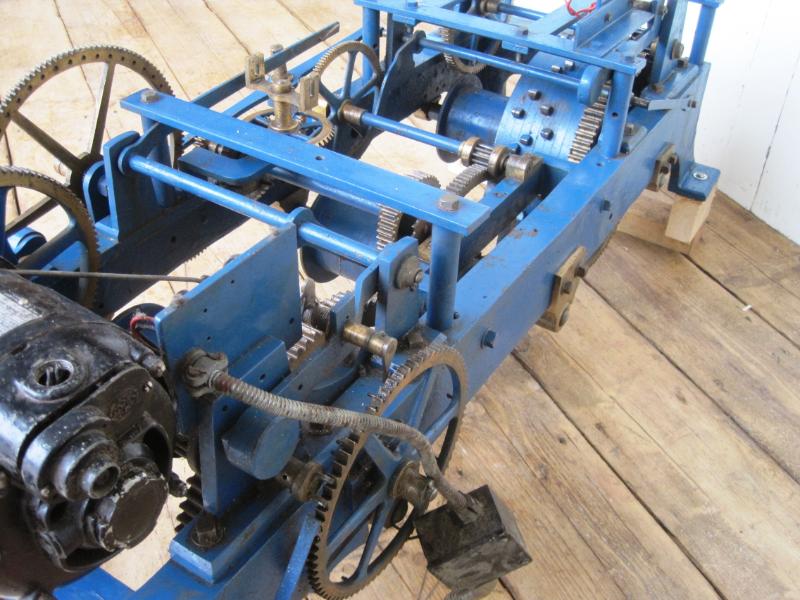
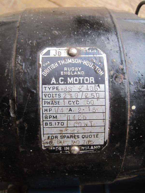
So I tracked down the only three train flat bed I could find for sale (at UK Architectural Antiques in Staffordshire) and went to see it. Unfortunately it was in poor condition or rather it had a lot of bits missing (most of what was there was in excellent condition) – it certainly wouldn’t go. It had been converted to electric drive at some point in the past (not recently) and this had been done in a very unsympathetic way. I don’t know who did this, it’s certainly not how Smith would do it now (totally non-destructive conservation grade conversions), but perhaps decades ago things were different. Not all of the electric conversion remained but it appears the striking and chiming trains had been directly driven by motors bolted to the cast iron frame with a lot of extra metal work. The going train had been driven by chain, probably from a synchronous motor. Although the motor was missing, I assume it used a synchronous motor because the pendulum, it’s large cast mount and the entire escapement was missing. On the striking train the fly was missing (as well as the arbor it should be on), the release and stopping mechanisms and one of the pillars for the fly arbor had been chopped in half to make space to mount the motor. Same story on the chiming train, plus the hammer levers were missing.

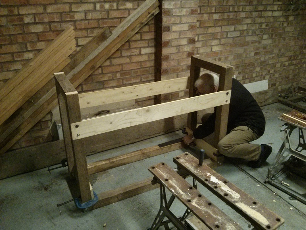
So begins the restoration project, which I shall be working on with my Father (who will be providing all of the skill and much of the brains for the project). We’ll have to see how much of it we can manage to do ourselves, I’m hoping we will be able to do most of it, maybe even all of it. After getting our hands on it, dismantling it for a thorough examination and inspecting every picture of a Smith clock we can find online we think we probably can do it and I plan to document the process here.

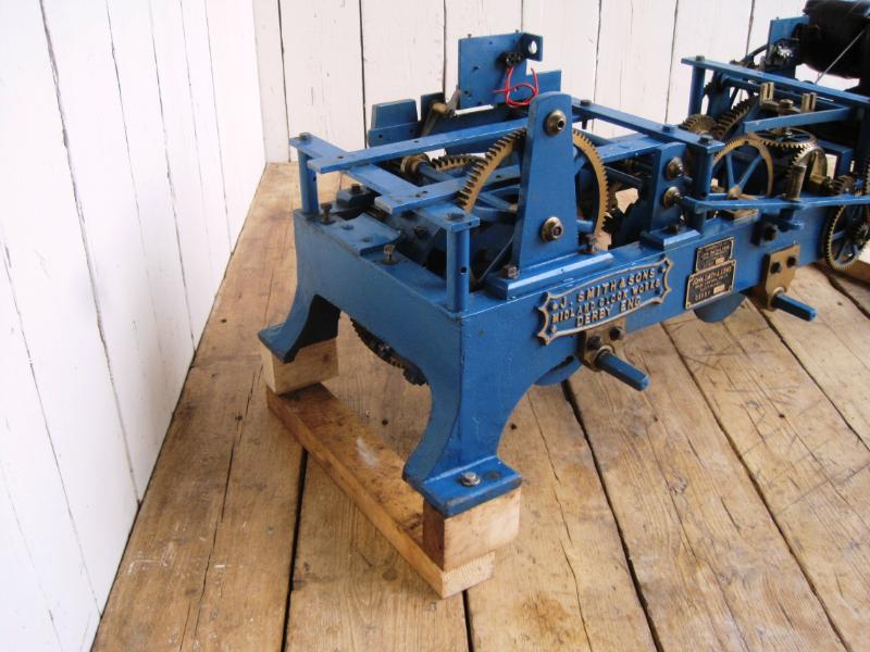
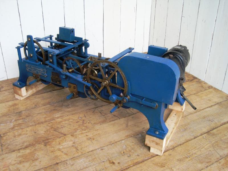
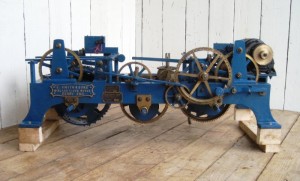
Original advert for the clock and sales pictures from UKAA (note just how big it is and how optimistic they were about the condition):

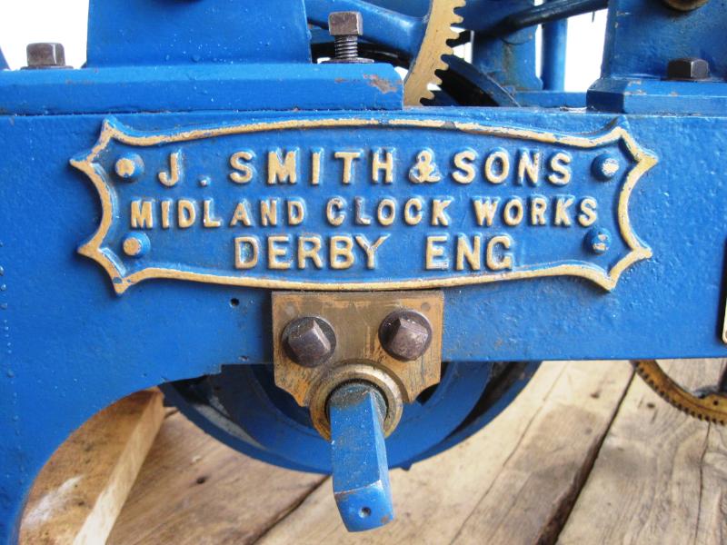
Cast Iron Turret Clock Movement – John Smiths Derby

  • The overall measurements with the frame are 55″ wide x 18½” tall x 24″ deep with the handle
  • Included is all of the parts in the pictures
  • This was purchased privately from Bournemouth
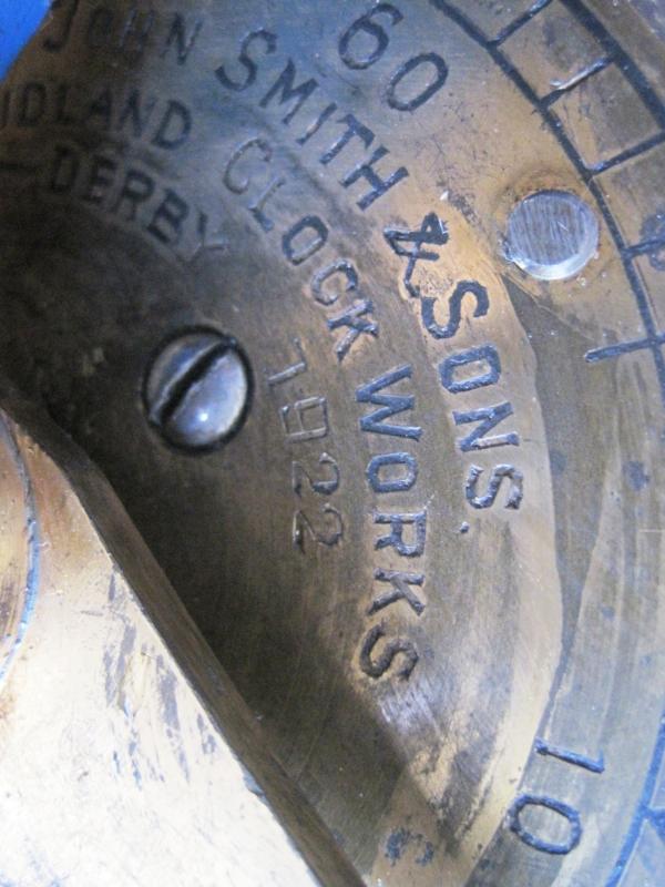
  • The clock was made by J Smith & Sons Derby Dated 1922
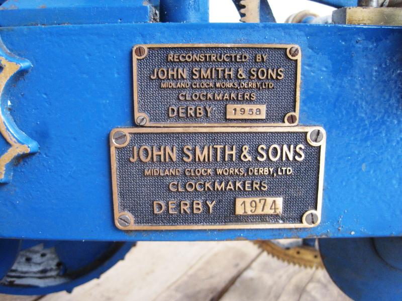
  • The clock was refurbished in 1958 and again in 1974
  • The clock was well greased and all the bushes etc feel good and tight – so i have no reason to think why this clock could not be up and running again without much fuss