Maintaining power

IMG_20150131_163813

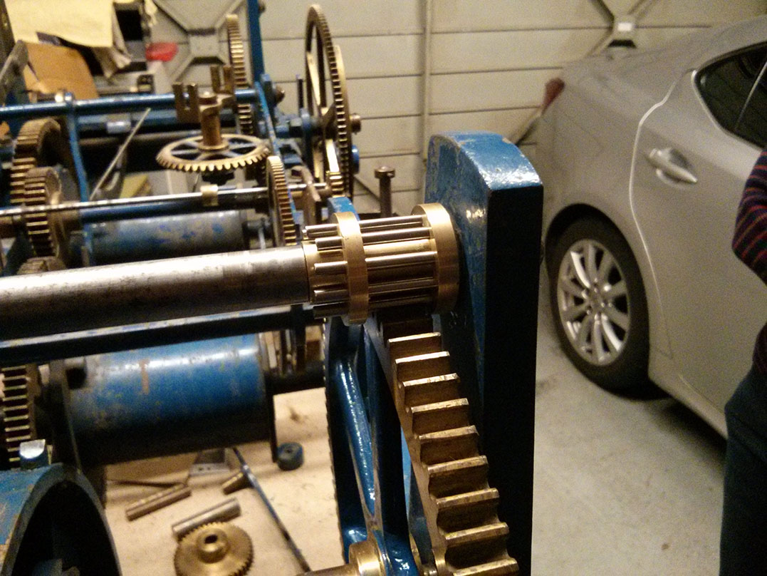
The maintaining power is a device for keeping the clock going while you wind it (and winding a turret clock can take a while). The type on this clock involves a weighted lever which must be lifted to allow the winding handle to be attached. Lifting the lever engages a pawl with the great wheel to apply force to the going train. The lever slowly returns to its resting position as the clock continues, by which time the winding should be finished.

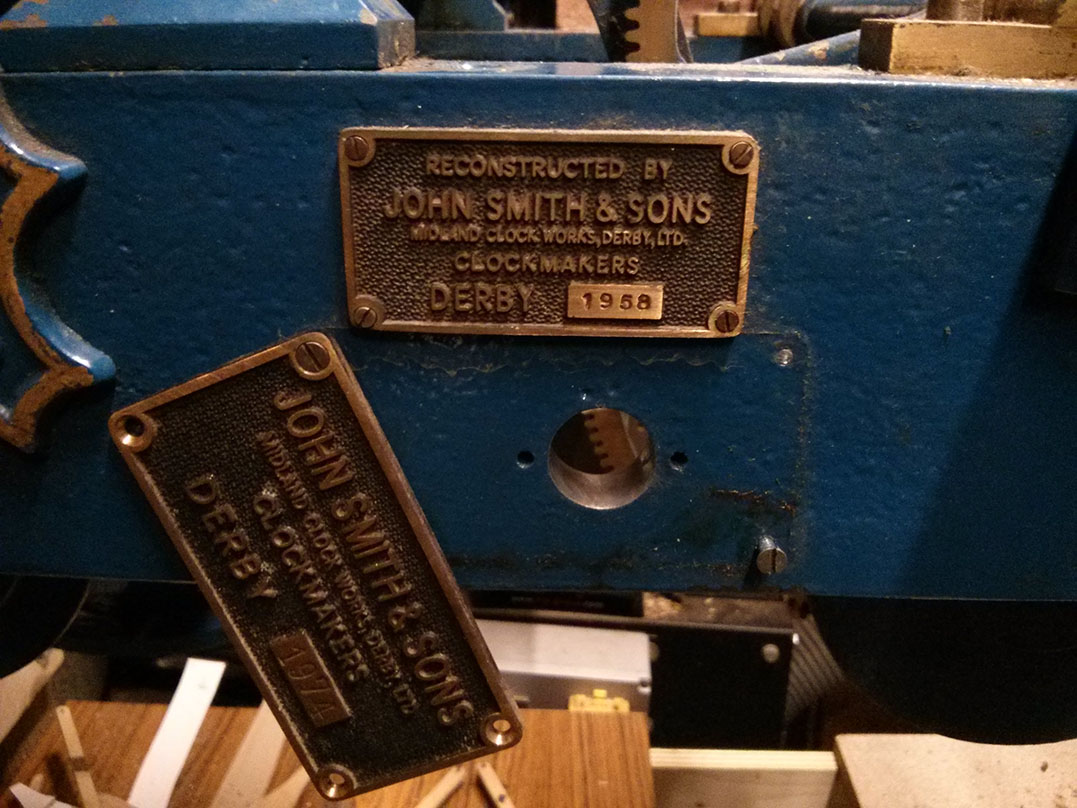
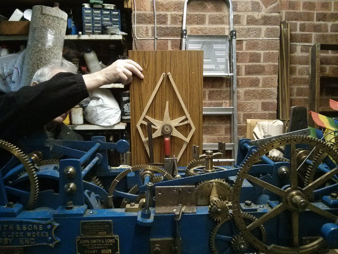
The hole at the front of the clock for the maintaining power arbour had been covered by a John Smith & Sons, Derby plaque, which was our only clue to the fact that Smith’s had done the conversion. Smith’s confirmed this was how it used to be done when my Father visited them.

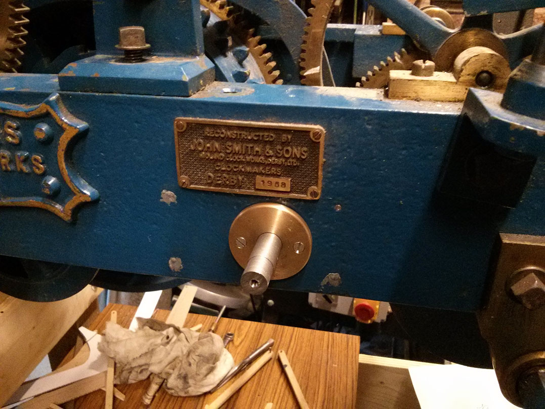
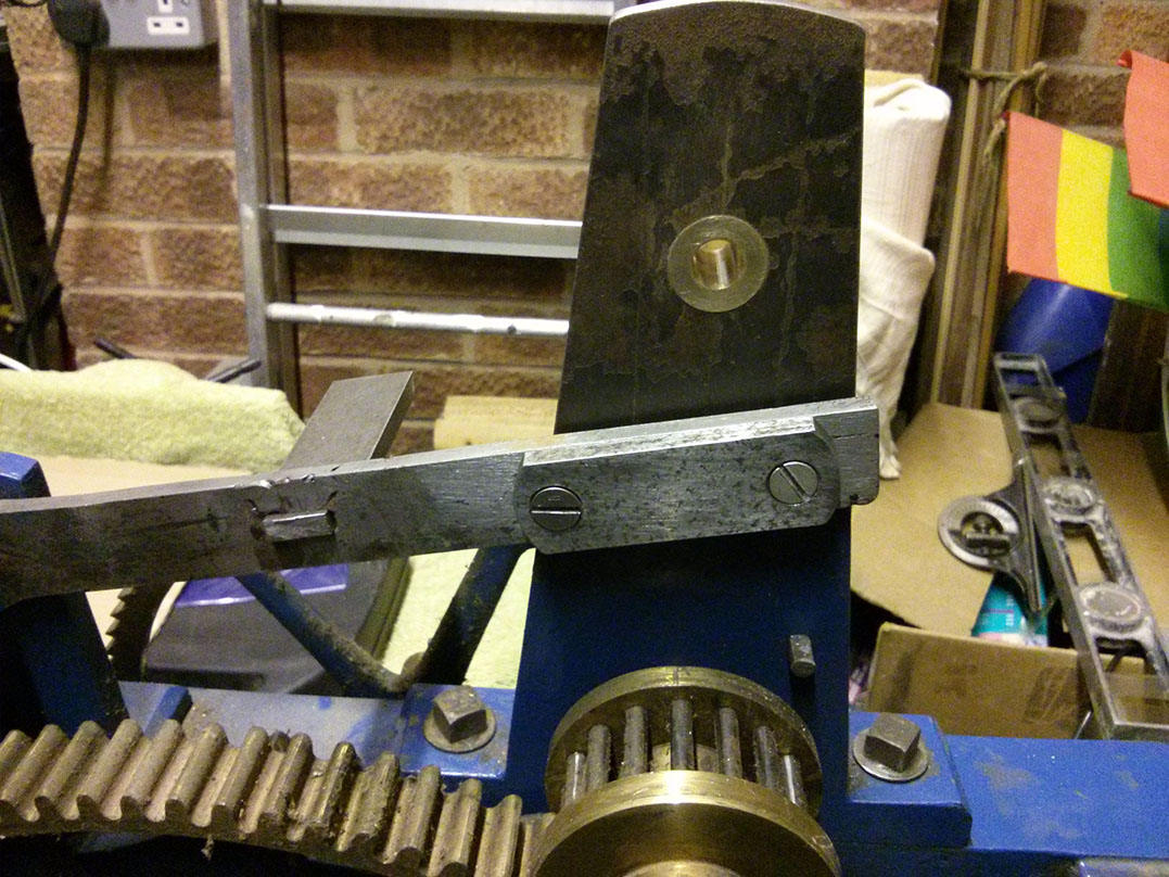
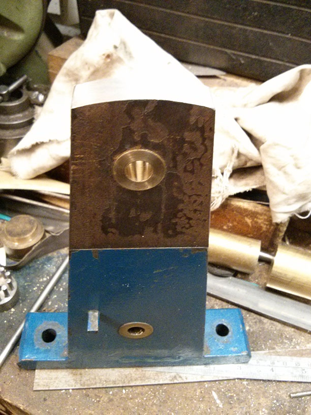
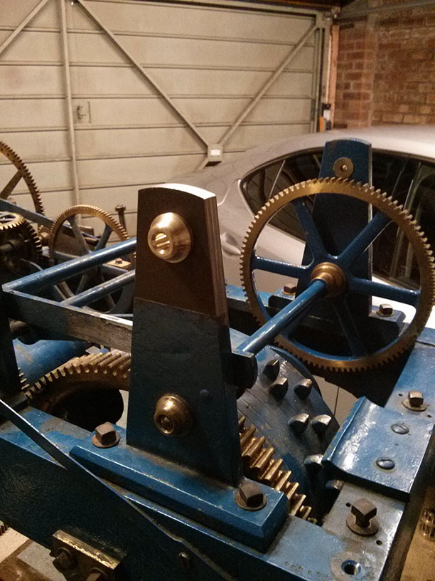
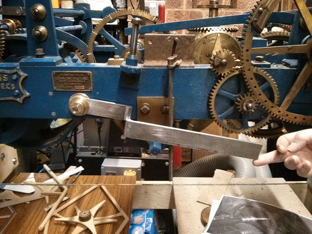
You can see in the pictures some liquid weld filling three of the bolt holes where the plaque was removed (the head sheared off the fourth). They look a bit ugly now but once they’re smoothed down and the clock is repainted you’ll never know there’d been a plaque there.

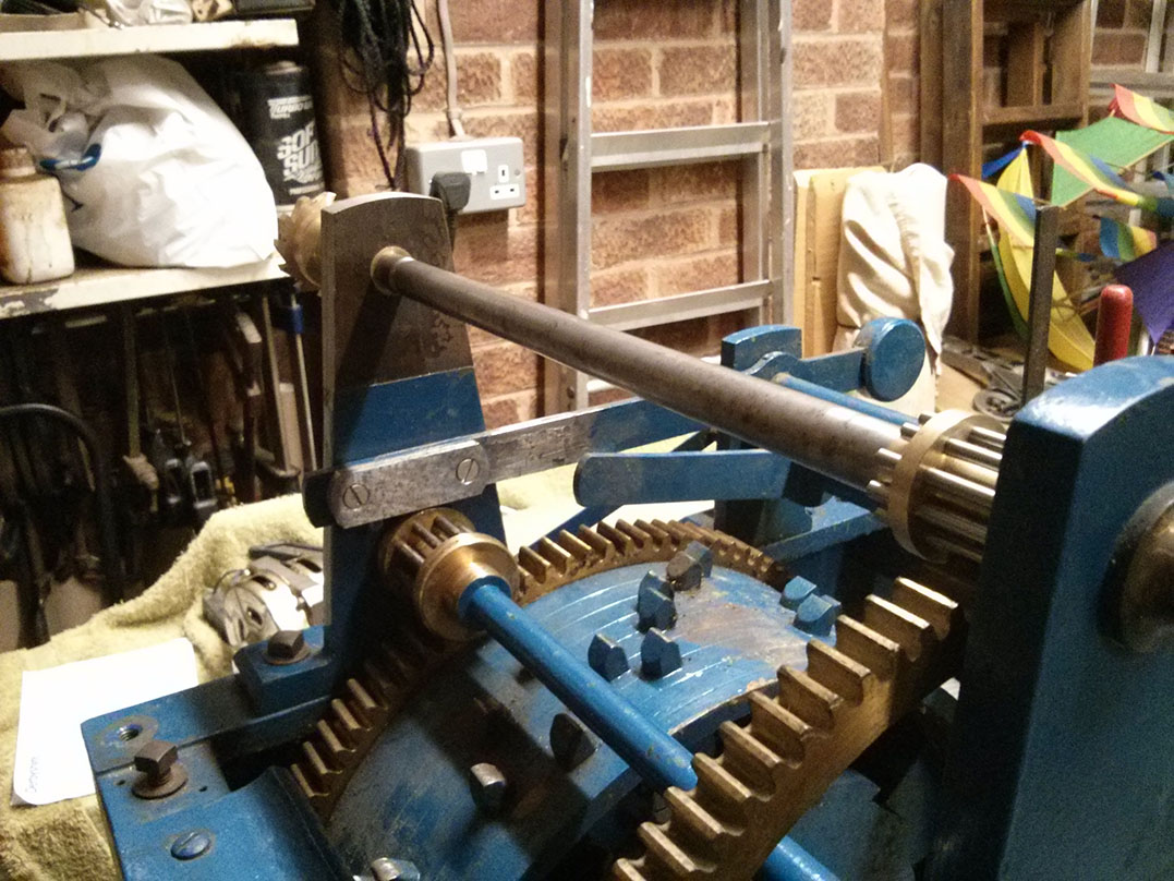
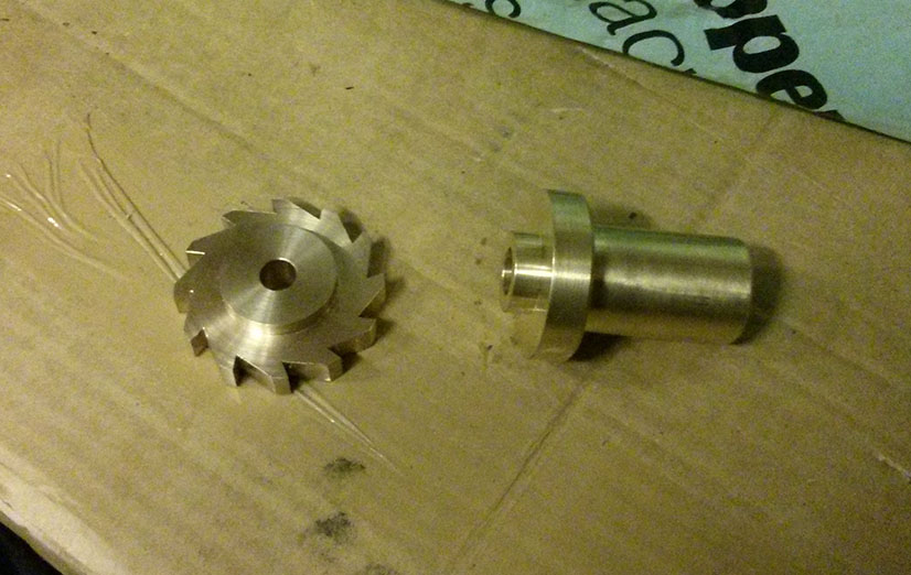
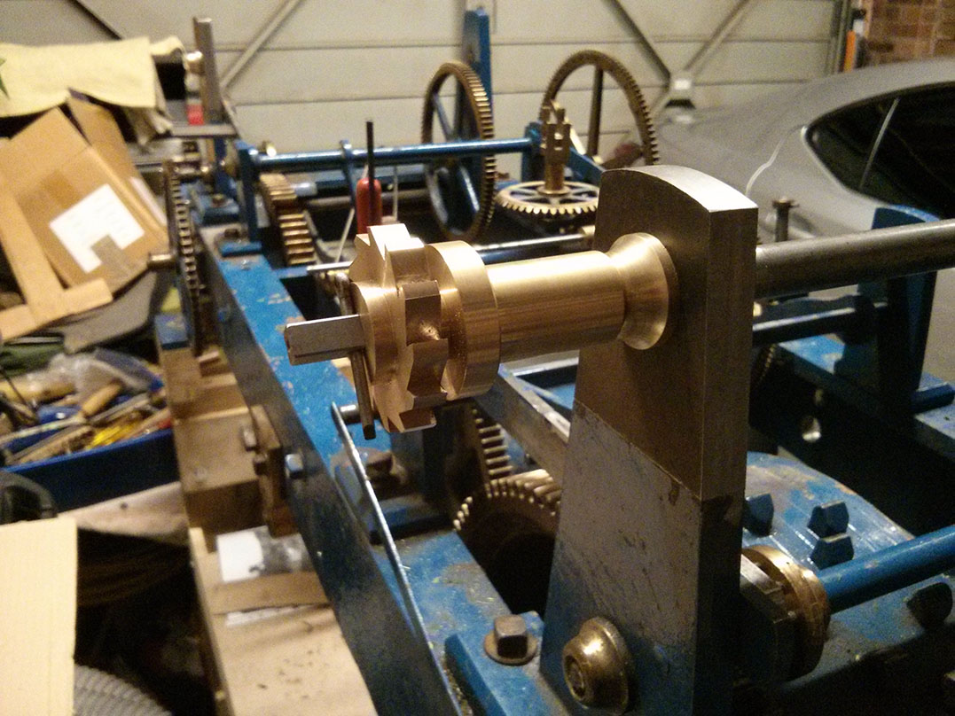
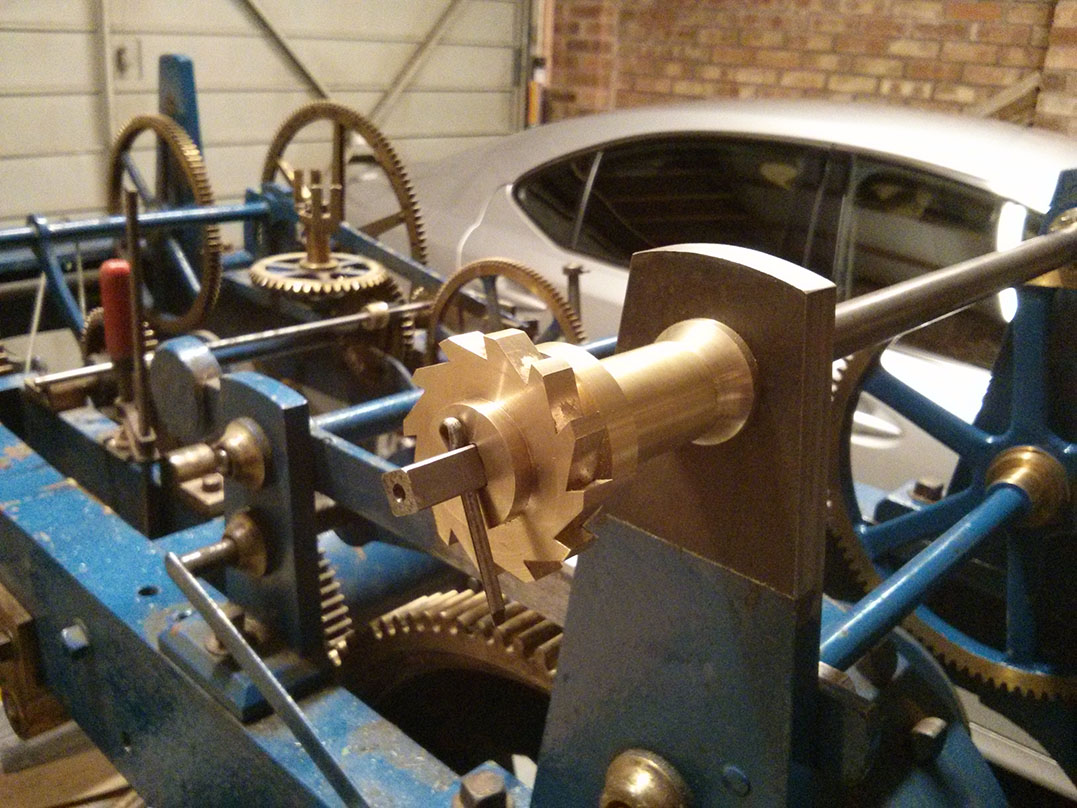
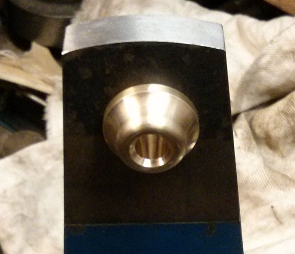
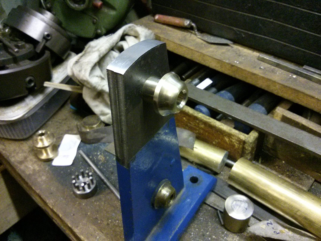
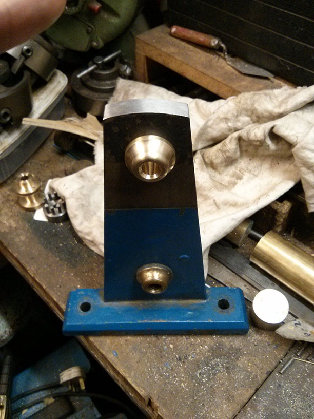
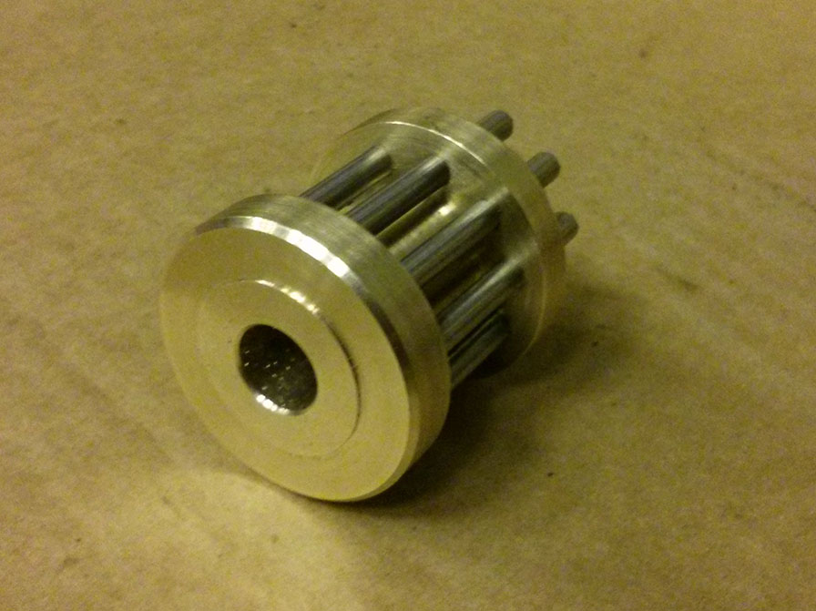
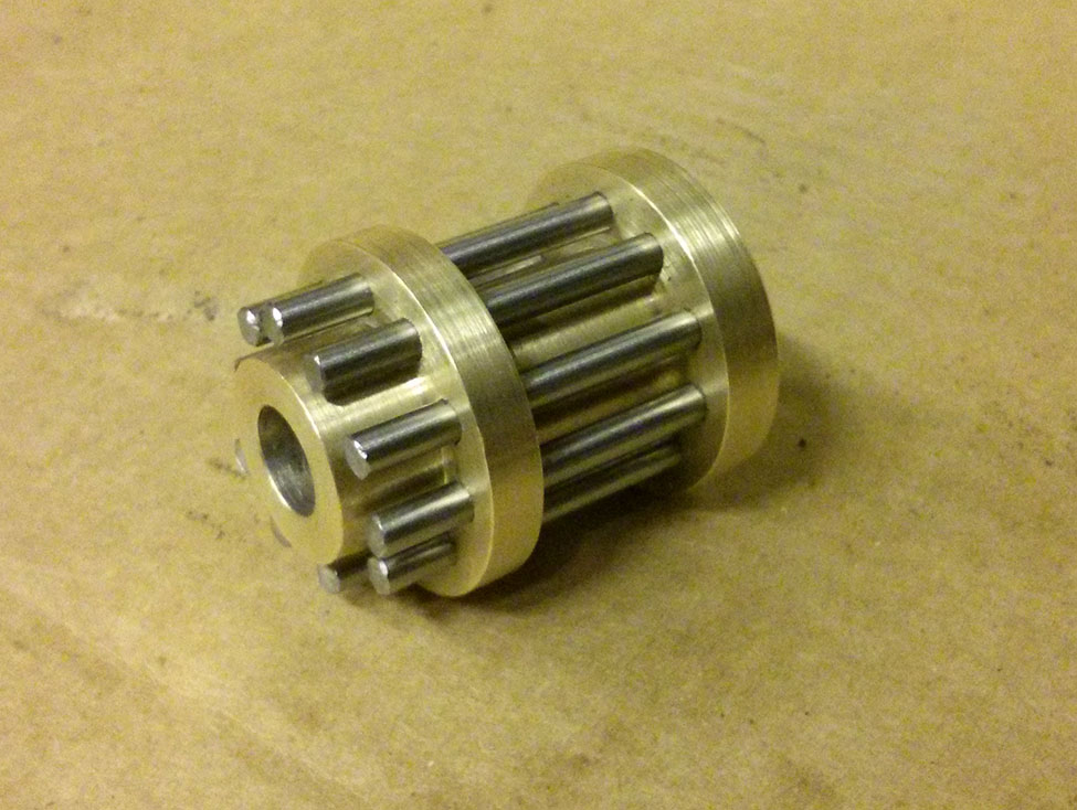
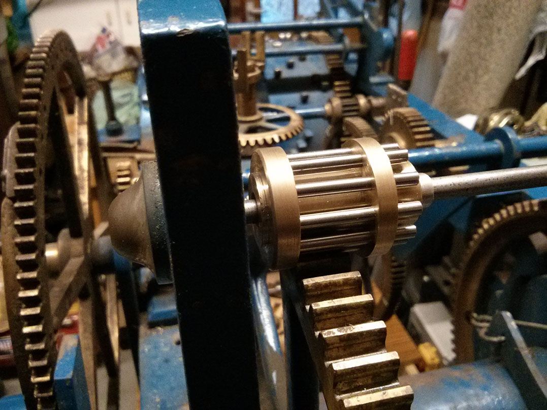
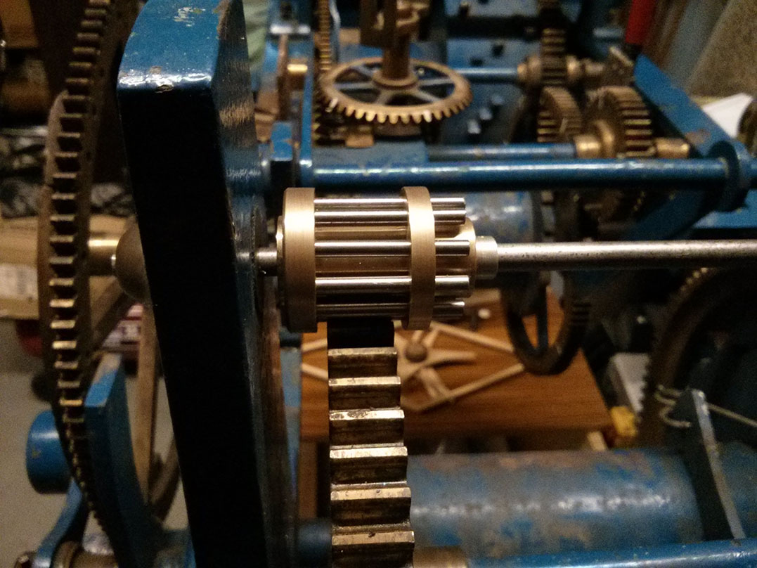
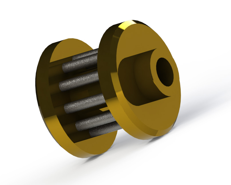
A new blush was made for the front and there isn’t one at the back (the arbour goes straight into a hole in the frame). There isn’t a great deal of movement here, but without a removable bush at at least one end there would be no way to get the arbour in and out.

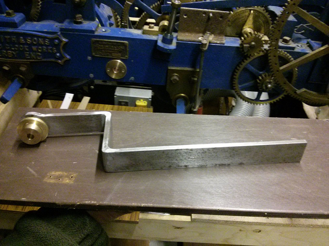
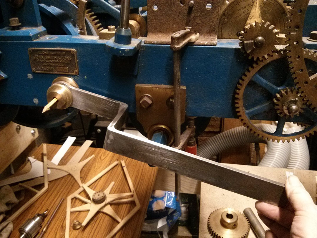
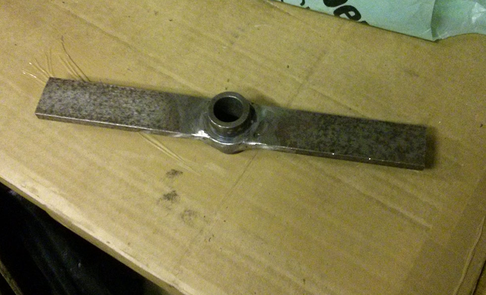
Then a cranked lever is attached to the squared off arbour and a fancy brass nut holds it all in place.

Next steps are the pawl, the weight on the end of the lever and a stop to prevent the lever going down too far.


Strike control mechanism

New "catch-plate" on the striking mechanism.

We’ve got a little bit more work done on the strike controlling mechanism (I previously called it the strike stopping mechanism, but of course it’s just as involved with starting the strike as it is with stopping it). The two “catch plates” (I don’t know if there is a proper horological term for these) had been removed. New ones have been made, but are not yet complete. To complete them they need two rectangular projections that interact with a third projection on a rotating arm attached to the fly arbour. We have also made the first of these rotating arms (minus it’s projection).

My father has seen this in action on his visit to Smith’s, and we have videos, but we still need to do some work on figuring out exactly how it works. An explanation of our current understanding follows…

Starting position before the clock begins to strike:

  • The horizontal arm in the first picture (with the new plate attached) is held just above the rest pin (visible just above the right edge of the lantern pinion). It is held there by the projection you see from the back of the arm (incomplete) being lifted by a pin on the wheel behind the frame. The 12 pins on this wheel are spaced increasingly far apart to control the number of strikes.
  • The rotating arm (third picture) on the fly arbour is always trying to rotate clockwise but is obstructed because the square block projecting from it is locked against the square block projecting from the catch plate.

The striking process:

  1. The horizontal arm is lifted briefly by the going train, on the hour.
  2. This unlocks the rotating arm attached to the fly arbour, so its projecting block can pass below the block on the catch plate.
  3. The fly arbour begins to rotate, which means the rest of the train moves too.
  4. Within the first rotation of the fly arbour the wheel with the pins at the back of the clock rotates and is no longer trying to lift the horizontal arm.
  5. The horizontal arm drops down, below it’s starting point and rests on the rest pin.
  6. The rotating arm is now able to rotate freely, its block now passing above the block on the catch plate.
  7. The clock strikes the required number of times.
  8. A pin on the wheel at the back lifts the horizontal arm.
  9. The block on the rotating arm collides with the block on the catch plate causing the arbour, and rest of the train, to stop.
  10. The fly, which is driven by a ratchet, continues to spin for several seconds, until it comes to a natural stop.

This explanation will probably be a lot easier to follow once we’ve completed it and have more pictures, or better yet a video. In the mean time these videos might help: a 1912 Smith clock in the US & the 1910 Smith clock at Trinity College, Cambridge.

Start of the new fly

IMG_20150117_171859

The fly is a kind of air brake that controls the speed at which the connected arbour can rotate. This in turn controls the speed of chiming or striking. Obviously the timing here isn’t nearly as critical as the going train. The fly goes on the same arbour as the lantern pinions made last week. Unfortunately this whole section of the train had been removed when the clock was converted to electric drive.

The fly on a turret clock can be pretty large – we think ours needs to be up to 28 inches in diameter. When the arbour stops turning (which happens suddenly) the fly needs to able to come to a stop gently. To enable this the fly is driven through a ratchet – when the arbour stops turning the fly can continue until it stops naturally.

Our new arbour is made of medium carbon steel and will eventually be hardened at the ends where is passes through the bushes. On one end of the arbour we have the new lantern pinion. On the other end the arbour extends out through the new bush and through a loose bush to which the fly will be attached. The arbour is then squared off to take a ratchet wheel. This wheel turns with the arbour and forces the fly to turn using the spring loaded pawls attached to the fly.

The pictures show the new arbour with lantern pinion (it’s not yet attached to the arbour so the pins haven’t been trimmed and the end hasn’t been closed), the new rotating bush and ratchet wheel in position.

New fly arbour bush

Close-up of new fly arbour bush

A bit warmer weather has meant it’s been possible to be working  in  the workshop again, so hot on the heals of the new lantern pinions yesterday comes a new bush for the fly arbour.

Rather than making it out of phosphor bronze, as you might normally for a bush, it’s machined out of brass. This is primarily because we didn’t have any phosphor bronze of sufficient size and it’s much more expensive to buy than brass. It’s a fairly substantial bush and the forces through it shouldn’t be too high (there is no force pushing the arbour against the wall of the bush, except for a little gravity), so it should be fine. If we’re wrong it’s not the end of the world, it’ll just have to be replaced when it wears.

The bush is a tight push fit into the arbour support pillar and was pressed in with a vice. Next it needs to be reamed out, using a reamer mounted on an arbour passing through the bush on the opposite pillar, to ensure perfect alignment.

New fly arbour lantern pinions

New fly arbour lantern pinion (chiming train), closed end view

We’re still putting some effort into the escapement, but not ready to try and make it yet. In the mean time the project hasn’t stalled – we now have two shiny new fly arbour lantern pinions.

These have been made the same way as the originals, with a push fit end “washer” (rather than the soldered end cap of our first attempt for the lantern pinion on the escapement arbour). According to the engineer at Smith’s these pinions should have 10 pins, that was very helpful information. We also know the positions of the arbours (relative to the wheels they engage with) because the front support posts were intact. With this info it was possible to work out the rest of the details.

The pinions for the striking and chiming trains are the same, except that the boss at the pillar end on the chiming train needs to be slimmer (the wheel it engages with is closer to the arbour support pillar).

The construction is basically one solid piece of brass. Both sets of trundle holes are drilled from the same end, so the holes are right through at one end and blind ended at the other. A tight fitting brass washer can be pushed on to the boss at the open end and the other end doesn’t need anything. The trundles are still over length to make it easier to pull them out, which will be necessary when the pinion is attached to the arbour (pinned through the centre).

The pinion has been modeled in SolidWorks –  see the image below and the technical drawing (fly_arbour_lantern_pinion_drawing.pdf). I don’t know if I’ll do this for all the components we make, it would be nice to do but possibly too much effort.

Next job is to make the bushes to go in the rebuilt arbour supports, ream out perfectly aligned holes and then make the fly arbours.

Prototype double three-legged gravity escapement

First prototype double three-legged gravity escapement

There is surprisingly little good information online about how to make a double three-legged gravity escapement. The details had to be pieced together from a number of old books (although some of these can be found online). Although there is information on how to draw out the basic shape there’s not much other detail. A leg length of 4 inches is mentioned in a couple of places, but without stating what size clock that is for. There is little information on material thickness and weight (obviously important on a gravity escapement), one book suggests cutting the parts out of the blade of a carpenters saw. As such, a prototype seemed like a good idea.

The first prototype is made of wood to test out the principal and give a better feel for the scale. The legs on the scape wheel are 4 inches long (8 inch diameter wheel), as mentioned in a couple of the books. From the second picture you can see this makes the escapement too large for this clock. However, the mechanism works nicely and it’s very satisfying to move the pallets side to side (by hand rather than by a pendulum) and watch the scape wheel advance. So we’re pretty happy with the design, we’ve just got to get the scale right now. Unless we can get some measurements from a real clock this will involve trying to take measurements from photos and using items like the arbour supports for scale (not exactly fool-proof).

The main books we used, which have with good info and diagrams:

  • Beckett E. A Rudimentary Treatise on Clocks, Watches and Bells For Public Purposes, 8th ed. London: Crosby Lockwood & Son; 1905.
  • Goodrich W. The modern clock; A Study of Time Keeping Mechanism; Its Construction, Regulation and Repair. Chicago: Hazlitt & Ealker; 1905.
  • Ferson E. The Tower Clock and How to Make It. Chicago: Hazlitt & Walker; 1903.