[ In keeping with the theme of the post, this article has been (almost entirely) written by AI. Basically I decided to test AI (Gemini) to see if it could do something useful for me, in an area I knew nothing about, and it actually did. ]
Source Code: https://github.com/raburton/wg-slaacer
WireGuard is an incredible piece of engineering—fast, modern, and significantly easier to manage than the IPsec/StrongSwan setup I previously used. However, while its simplicity is its greatest strength, that same design philosophy creates a unique challenge when it’s time to play with IPv6.
The Background: Why WireGuard Struggles with Dynamic IPv6
In the IPv4 world, we are used to scarcity. We assign a client a private internal address (like 10.0.0.2), NAT it, and call it a day. IPv6 changes the maths; we have addresses in abundance, and the standard way for a device to get one is SLAAC (Stateless Address Autoconfiguration).
The Problem: The “AllowedIPs” Routing Table
WireGuard doesn’t just use AllowedIPs for security; it uses it for routing. When the server sends a packet back to a peer, it looks at the destination IP and finds the peer whose AllowedIPs matches.
This creates a conflict with SLAAC:
- The /64 Requirement: SLAAC requires a /64 prefix to function.
- Overlap is Forbidden: You cannot have the same range in the
AllowedIPs of two different peers.
- The Waste: If you have 10 clients, you’d technically need to give each their own /64 prefix. While I get a /56 from my ISP (256 prefixes), dedicating a whole /64 to a single phone is incredibly wasteful.
- No “Learning”: Standard WireGuard expects you to know the client’s IP in advance. SLAAC expects the client to pick it on the fly.
The Solutions?
- Stick to Static IPs: Works, but you lose privacy extensions and the “plug and play” nature of IPv6.
- One Interface Per Peer: Creating
wg0, wg1, etc., is a management nightmare.
- Modify the wireguard kernel module: In hindsight maybe not as difficult as I first assumed, esp if using AI, for another day…
- Others: I found several other discussions online with hints at solutions, that ultimately made no sense in practice.
The New Solution: eBPF to the Rescue
If the WireGuard kernel module won’t learn IPs dynamically, I decided to teach it. How? I had ideas that didn’t work, and talking those through with Gemini it suggested using eBPF (Extended Berkeley Packet Filter).
How it Works
The solution consists of a C program that loads a kernel probe and a userspace daemon.
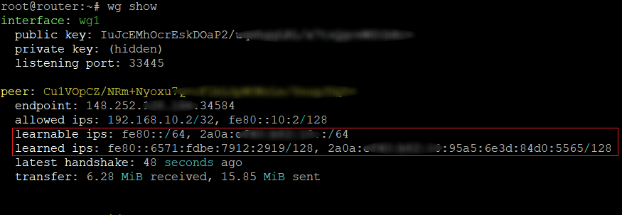
- The Kernel Probe (
provisioner.bpf.c): This hooks into wg_allowedips_lookup_src. Every time WireGuard validates a source IP, our code triggers. It extracts the IPv6 source, verifies the packet came from our interface (e.g., wg1), and “walks” the kernel’s internal wg_peer structures to find the peer’s public key.
- The Userspace Daemon (
provisioner.c): When the BPF code sees a new IP, it sends an event to this daemon. The daemon then calls the WireGuard Netlink API to dynamically add that specific /128 address to that peer’s AllowedIPs list.
Security and The “Learning” Model
Moving from a static model to a learning model changes the security contract, but for a home user with trusted peers, the risks are well-managed:
- Cryptographic Enforcement: An attacker cannot just spoof an IP; the eBPF program only learns an IP if the packet has already been successfully decrypted by a peer’s private key.
- DoS Protection: The code uses a token bucket to rate-limit how many new IPs a peer can register, preventing a buggy or malicious client from flooding the routing table.
- Future Hardening: While not in the current version, “scoped learning” could be added to ensure the learned IP stays within a specific prefix. Furthermore, a firewall on the other side of the WireGuard interface can easily block any spoofing attempts into the rest of your LAN.
Reflections on “Vibe Coding”
This project was as much an experiment in “Vibe Coding” as it was in networking. As a programmer, I used AI to bridge the gap into the unfamiliar territory of eBPF.
I like to learn by example, and AI provided the direct, relevant examples I needed instead of requiring me to scrape documentation and examples for days. However, it wasn’t a “hands-off” process. I had to intervene frequently—debugging hallucinated kernel structures and refining the logic.
Without a programming background, I don’t think I could have steered the AI to this specific result. But with it, I was able to maintain the “vibe” of the goal while the AI handled the heavy lifting of the boilerplate. The result is a high-performance auto-provisioner that makes IPv6 on WireGuard feel as seamless as I had hoped it could be.