Our going train

Diagram of the going train

It occurs to me I haven’t actually documented our going train yet. So here it is, complete with the unknowns.

Interestingly most of the Smith clocks I’ve looked at online have 100 teeth wheels where we have one of our 120s (the one that isn’t the great wheel). Unfortunately I don’t know what the rest of the train is like in those clocks because the pictures aren’t good enough to follow them through.

However, I’ve recently found one interesting clock that might be close to ours, at least for the going train. The clock at Trinity College Cambridge is a curious 1910 Smith clock with two striking trains. It first strikes the hour on one bell with one striking train, then again on a second bell with the second striking train. The site offers no explanation as to why it does this (except to say that the previous clock also did it). From the pictures it appears it has a 120 tooth wheel in the same position as ours and a 72 tooth wheel at the escapement. It has a 60 second rotation of the arbour, complete with dial and second hand. The pendulum length is stated as 2m, which is a bit odd (just short of 1.5 seconds), but there is mention of a 1.5 second swing in the explanation of the escapement. It appears to have a team of enthusiastic engineers looking after it so I’m optimistic I might get some useful info back if I make an inquiry… Update: unfortunately they didn’t reply at all.

Strike stopping mechanism

IMG_20141223_172328

Another job started while we think about the escapement (and of course Christmas is distracting). The strike stopping lever had been kinked to pass on the outside of the arbour support post. This has been straightened back out.

It had also had an extra chunk of metal welded to the top to take part of the electrical switching mechanism for the motor. This has been removed. The original projection had been ground off just below this position, leaving the metal a little scruffy beneath the paint. In the picture you can see a temporary new projection loosely in place. The rest of this (the downward part to be pushed by the pins) can’t be finished until we get a bit more of the striking mechanism replaced.

A weight had also been added to the end, attached through one of the existing holes for the catch plate. Easily removed.

The lever seems to have been shortened a bit too, it should (presumably) have a nicely rounded end like the one on the chiming mechanism. Currently the end is straight, but not quite at 90 degrees – I’m sure this can’t be original. This can be repaired last, when we’ll know just how much metal to add to get the balance perfect.

This is now much closer to original, although still not finished. Compare with how it looked, from the opposite side, when purchased (also note the arbour support that has now been rebuilt):

View of striking train, as purchased

Double three-legged gravity escapement

Diagram of double three-legged gravity escapement

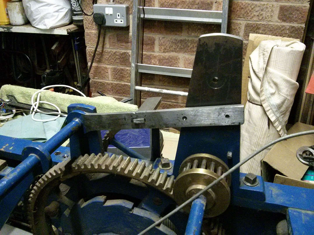
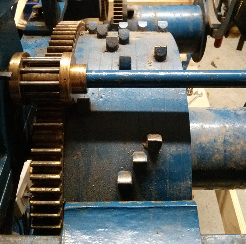
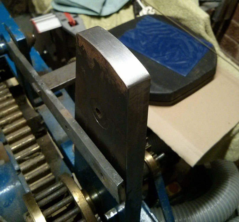
As previously mentioned the visit to Smith of Derby revealed that our clock would have had a double three-legged gravity escapement, not the pin wheel we were expecting. The clue was apparently the extra rail inside the back edge of the frame (cast iron, bolted on) to which the arbours attach, seen here at the bottom left of the picture.

View of going and chiming trains, as purchased

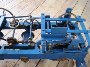
On an equivalent Smith pin wheel clock this extra rail is not there and the arbours extend right to the back rail of the main frame.

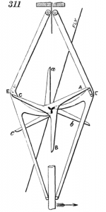
The double three-legged gravity escapement is better at time keeping, especially on a turret clock. The impulse to the pendulum is not affected by any forces in the going train, so large hands covered in snow do not affect its accuracy. It was invented by Edmund Beckett for use in the clock commonly known as Big Ben.

While we hadn’t quite worked out how to make the pin wheel escapement, we think this one is going to be harder. As with a much of this project it’s the unknowns that make it difficult. We had studied all the pictures we could find of Smith pin wheel escapements and worked out a fairly plausible pin count and pendulum length. Now we have to do this again, but this time there are more variables.

Time for a couple more bits of useful info my Father got from his visit to Smith’s:

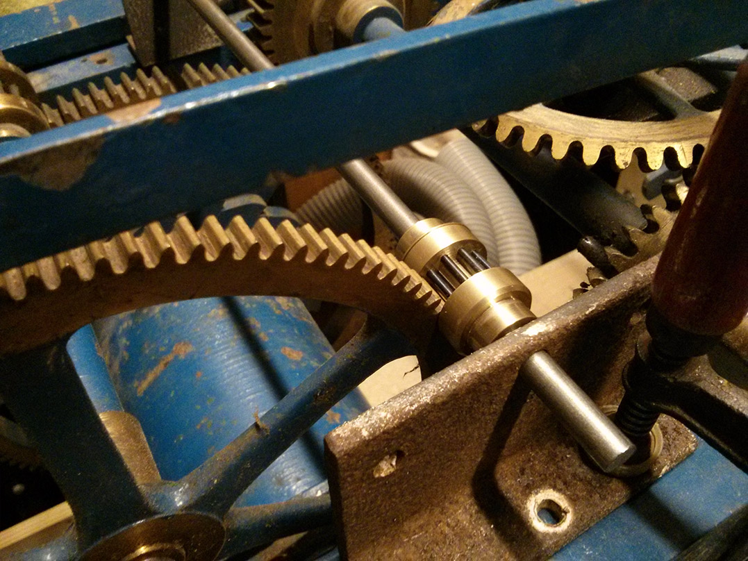
  • The arbour we need to replace in the going train should rotate once per minute. You can put a small dial and a second hand on the end of it if you like. Since hearing this I have found an image of one that has a second hand.
  • It was suggested that the clock probably had a 1.5 second pendulum and a 90:9 ratio coming off the escapement.
  • All these old clocks were a bit custom made, they didn’t stick to plans (probably for good reasons at the time). This means there are no suitable plans that they could give us for a clock of this date. It also means that any info taken from another clock may not apply to this one.

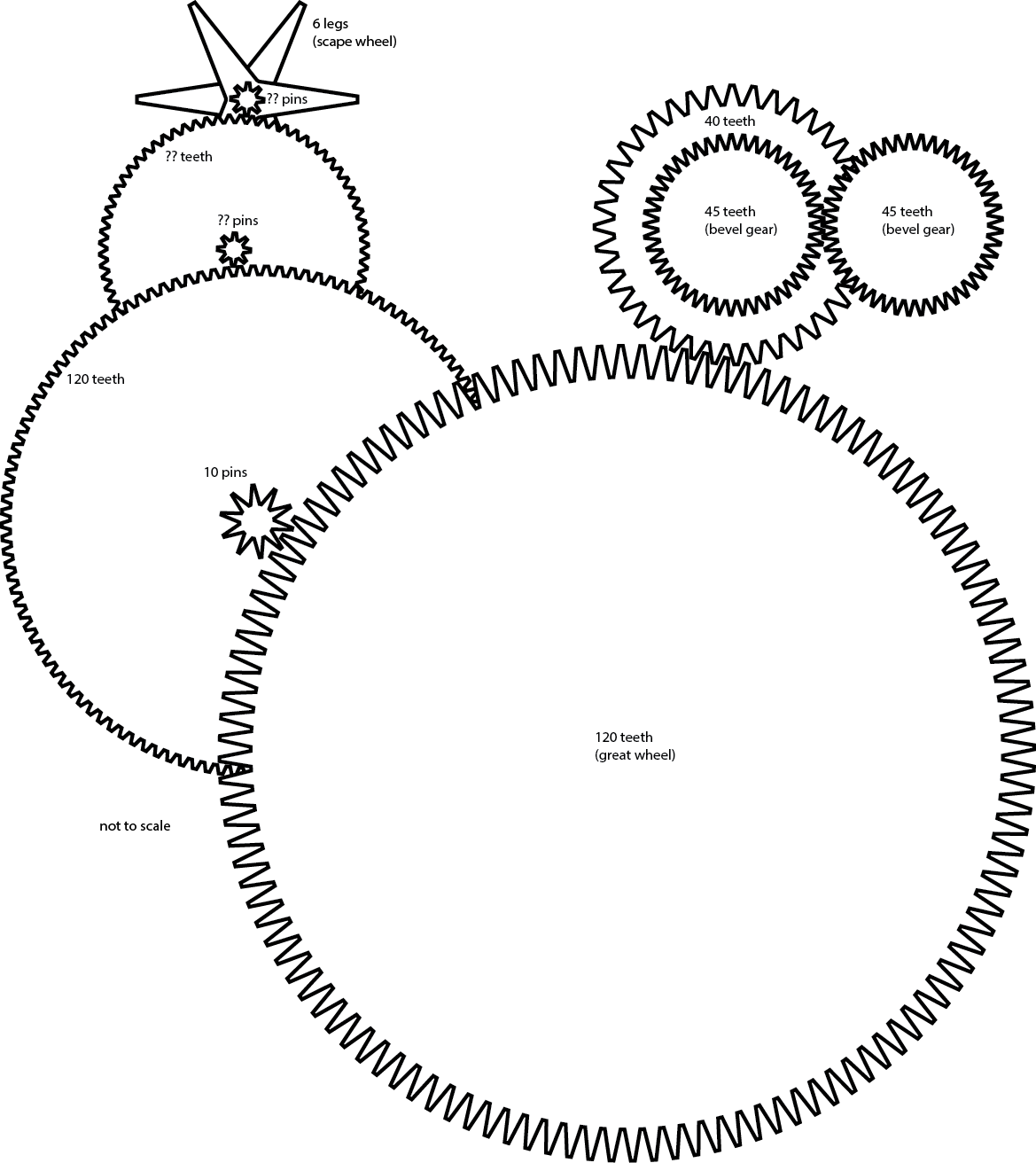
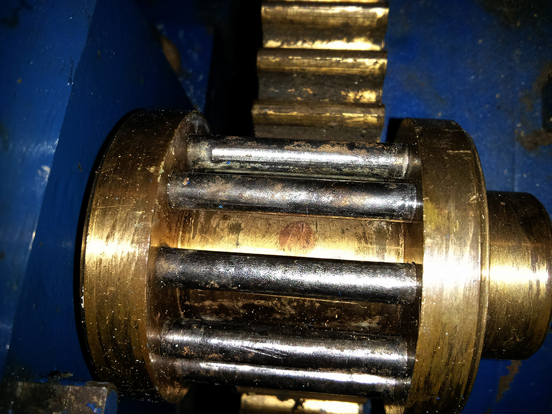
Trying to put the first two facts together does not seem to fit and that’s where the third probably comes in. By my maths (which is not infallible) a 1.5 second swing advances the scape wheel a 6th of a rotation, which means 9 seconds per complete rotation. Turning a 9 pin lantern pinion against a 90 tooth wheel (a 1:10 ratio) means a 90 second revolution for the arbour, not the 60 you’d need to put a second hand on it. We need to move the next (existing) wheel in the train one tooth every 7.5 seconds, which would be possible if we had a 12 pin lantern pinion (instead of the 10 pin we have already made). So this is workable, but doesn’t give us a 60 second rotation of the arbour.

I’ve played with various permutations to try to incorporate as much info as we have, while still driving the rest of the train at the correct rate. The sensible options seem to be:

  • 1.5 second swing, 90:9 ratio, 12 pin lantern – gives a 90 second rotation of arbour (as worked though above).
  • 1.25 second swing, 90:9 ratio, 10 pin lantern – gives a 75 second rotation of arbour.
  • 1.25 second swing, 72:9 ratio, 8 pin lantern – gives a 60 second rotation of arbour.
  • 1.125 second swing, 90:9 ratio, 9 pin lantern – gives a 67.5 second rotation of arbour.

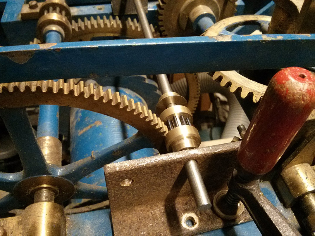
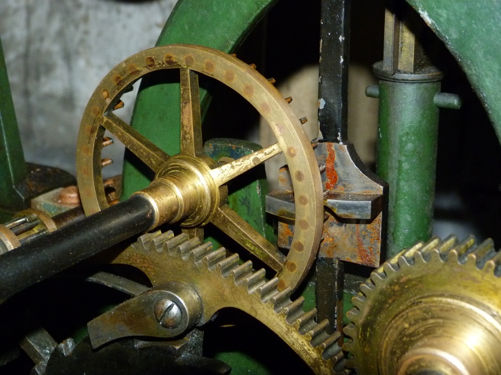
The engineer my Father spoke to at Smith’s sent him a picture of an escapement that probably comes from a similar clock. From what my Father told me it sounds as though they have a database of clocks they maintain, with pictures, and he looked up what he thought should be a pretty similar model. It’s difficult to count the teeth exactly in the picture, because you can only see a couple of sections of it, but it appears to have a 72 tooth wheel. Unfortunately you can’t see enough pins on the escapement lantern pinion to count them.

A visit to Smith of Derby

4695_1

My father emailed Smith of Derby to see if they could help us identify where this clock had been installed and if they had any information about it that could help us recreate the missing parts. As we are local to Derby he was invited over to look at a similar three train clock they had in their workshop. They very kindly allowed him to take measurements and photos and one of their engineers answered his questions and supplied some printed information.

Unfortunately they weren’t able to tell us where the clock had been. It doesn’t have any kind of serial number so tracking it down based on “I was told it came from Bournemouth” was rather a long shot.

We did learn lots of useful things though, probably the most important being that the clock did not have a pin wheel escapement as we thought – it would have had a double three-legged gravity escapement.

Another thing we discovered is that they likely did the electric conversion. That was a bit of a surprise. I guess it was done in the 70s (there is a Smith plaque, dated 1974, over the hole where the maintaining power should have been) and lots of dodgy things were considered the norm back then. If you have a clock you’d like motorised be assured that’s not how they do it anymore!

I’ll mention other bits of info picked up on the visit in appropriate posts as they crop up.

Decoding the chime barrel

IMG_20141222_155430

This clock has quite a large chime barrel compared to many of the turret clocks I’ve found online – it has 8 positions across the barrel meaning it uses 8 bells. But what’s the tune?

There are 4 pins on the side of the barrel (actually only 3 are intact, a little of the forth has a remains snapped off in the threaded hole which might be a pain to get out). These stop the chime when the end of the tune is reached. This suggests that the barrel rotates once per hour and plays at all 4 quarters. This might sound obvious but apparently the East Garston church clock has two copies of the tune on the barrel and only rotates once every two hours (presumably there 8 pins around the edge). The pin stops the chime when it reaches the top and the projections that move the hammer levers (I’m sure these must have a proper name) do so at the edge of the frame. So with barrel positioned with a pin uppermost there should be a gap in the projections where the hammer levers can rest between quarter hours. Our hammer levers and the bracket for them is missing – something else to make! Our 4 pins are all spaced increasingly far apart, suggesting the tune gets longer each quarter hour and so making it easy to see which section is which quarter.

Now starting from the gap before the shortest quarter we simply wrote the position of each projection (1-8, left to right as viewed in the picture) and the length of the gap after it in beats. The most common gap was 3/4 of an inch, so we defined this as one beat. You can’t tell how long the last note is because nothing follows it.

Next job was to consult a list of clock chimes. We used the ‘Watch & Clock Encyclopedia’ by Donald De Carle, 1959. There are a surprising number of chimes but they are listed by number of bells and if you count how many notes are in each quarter it’s pretty easy to work out what you’ve got (assuming it’s in the book of course). We mapped the notes to the barrel projection positions and the whole thing fits perfectly, as did the timings. Ours was actually the first 8 bell chime listed – Guildford chimes.

According to the book Guildford chimes were composed in 1843 by George Wilkins for Holy Trinity Church, Guildford.

A new lantern pinion

IMG_4773

This is our first real new part for the clock. This 10 pin lantern pinion is on the escapement arbour and engages with a 120 tooth wheel. The actual arbour and the rusty support in the picture are just temporary.

The bulk of it is made from a single peice of brass. Both sets of holes for the trudles were drilled in one go from one end. This means only one end cap is needed.

The end cap is a separate piece which we intend to solder on, which is how we initially thought the originals were made. Rather than just a washer to cover holes we made a complete end cap, it seemed easier to make that way.  We need to be careful to not get the trundles too hot else they’ll loose their temper. How easy will it be to separate it again in the future to replace a worn pin though? Once the end cap is attached it will be turned down to a perfect match to the body of the pinion.

Lantern pinions

IMG_20141221_133724

In order to faithfully reproduce the original parts we needed to work out how they were actually made. This took a bit of time to work out for the lantern pinions. On initial inspection it wasn’t obvious how they were attached to the arbours, but this turned out to be because they were so dirty and the original fixing was so neat. When we got one cleaned up we finally found a bronze pin in the centre of the pinion. This appeared to have been machined smooth and so blended in really well (hence any dirt, or insufficient light in the workshop, and it was invisible). It shows clearly it the image, but that’s zoomed in, taken with bright flash and I’ve tweaked the colours too so it’s easier to see than looking at the real thing.

However, this pin is beneath the trundles (the pins along the pinions, which engage with the teeth of next wheel in the train) which must have been inserted afterwards, yet the pinions ends aren’t open! This suggested it was made as two separate ends and the trundles sandwiched between them, but then you’d need two pins to hold the ends to the arbour. Only after closer inspection of another lantern pinion on the clock did my Father spot that there were end caps on the pinions. They are basically very well fitting brass washers pushed on to the end to cover the holes containing the trundles (at first we thought they might be soldered on, but apparently they are just pushed on). They are then machined to a perfect fit with a bevelled edge that masks the joint line. On one of the larger pinions there is a small gap where the hole in the washer isn’t a perfect fit around the arbour which gave it away. The result is really neat and serves to emphasise the quality of the original clock.

Escapement

P1080535_zpscfae8fcf.jpg~original

Logically one of the first things we want to get sorted is the going train – no point being able to chime before it can tell the time (although we did already take a slight detour with the arbour supports). To do this we need to replace the following missing parts:

  • the pendulum stand
  • the pendulum
  • the escapement
  • the escapement arbour and lantern pinion

This involves many unknowns. We don’t know the length (and so the period) of the pendulum. We don’t know what kind of escapement it should have. From looking at many similar Smith clocks on the internet (we are yet to find one identical) we are pretty sure it uses a pin wheel escapement. We don’t know how many pins, although most we have seen have 35 pins. We don’t know how many trundles the lantern pinion (opposite end of the arbour to the escape wheel) should have, no clear pictures found on the internet.  However, we do know that the next wheel in the train has 120 teeth, and needs to make 4 full rotations per hour, so we can work backwards to make some sensible suggestions for our unknowns.

120 teeth rotating 4 times per hour makes 480 teeth per hour. With 3600 seconds per hour we need to move one of these teeth every 7.5 seconds. Some measuring of the teeth on the 120 wheel suggest a lantern pinion with 10 trundles. If we assume 35 pins on the escape wheel we have enough information to work out a pendulum length: 7.5 seconds x 10 trundles = 75 seconds per rotation of the escapement arbour. 75 divided by 35 ~= 2.14 seconds for a full swing (back and forth) for the pendulum, which translates into a pendulum length of 1.14m.

Picture is of the escapement of South Mymms Church clock, J Smith & Sons (Derby) ~1892, taken by Harald Mueller.

Rebuilding the cut off arbour supports

IMG_20141202_113448

When the clock was converted to electric drive the back arbour supports were cut down. As the fly was no longer required (in fact it needed to be removed to connect the motors) these post could be cut down to make room for the motor to be mounted.

This seems like a terrible way to do the conversion. The Church Buildings Council of the Church of England provides guidelines on maintaining turret clocks which states, with regard to auto-winders and electric drives, “No parts should be removed from the movement.” and “There should be no cutting or drilling of the clock frame.” It’s likely that this conversion was done a long time ago, long before these rules were written, and was probably just how things were done then.

As they are cast parts welding a piece on top wasn’t going to be easy. Instead the top has been milled perfectly flat and an extra chunk has then been bolted to the top. The sides of the new piece were then milled to match the existing sides. The holes were plugged by hammering in a core of the same steel and the top shaped by hand to match the existing pillars. A hole was then bored to take a new bush (not yet made).

Building a clock stand

IMG_20141204_161400

Working just above floor level wasn’t going to be very comfortable, and you need space underneath the clock to get the barrels out, so a stand was needed. This was made from wood we had on hand, all we needed to buy  to make this was a few extra coach screws. The stand needs to be pretty strong as big cast iron framed turret clocks are heavy (not sure exactly how much this one weighs, we must try and weigh it at some point) and so are the weights and the pendulum . The uprights are 3×3 inch and the the stand is rock solid. As we don’t yet know the pendulum length we made it plenty tall enough and then mounted it on the original wheeled boards I got with the clock. The result was a little too high to work on comfortably so we ended up having to shortening the uprights a little.