Category Archives: Turret Clock

The clock is ticking…

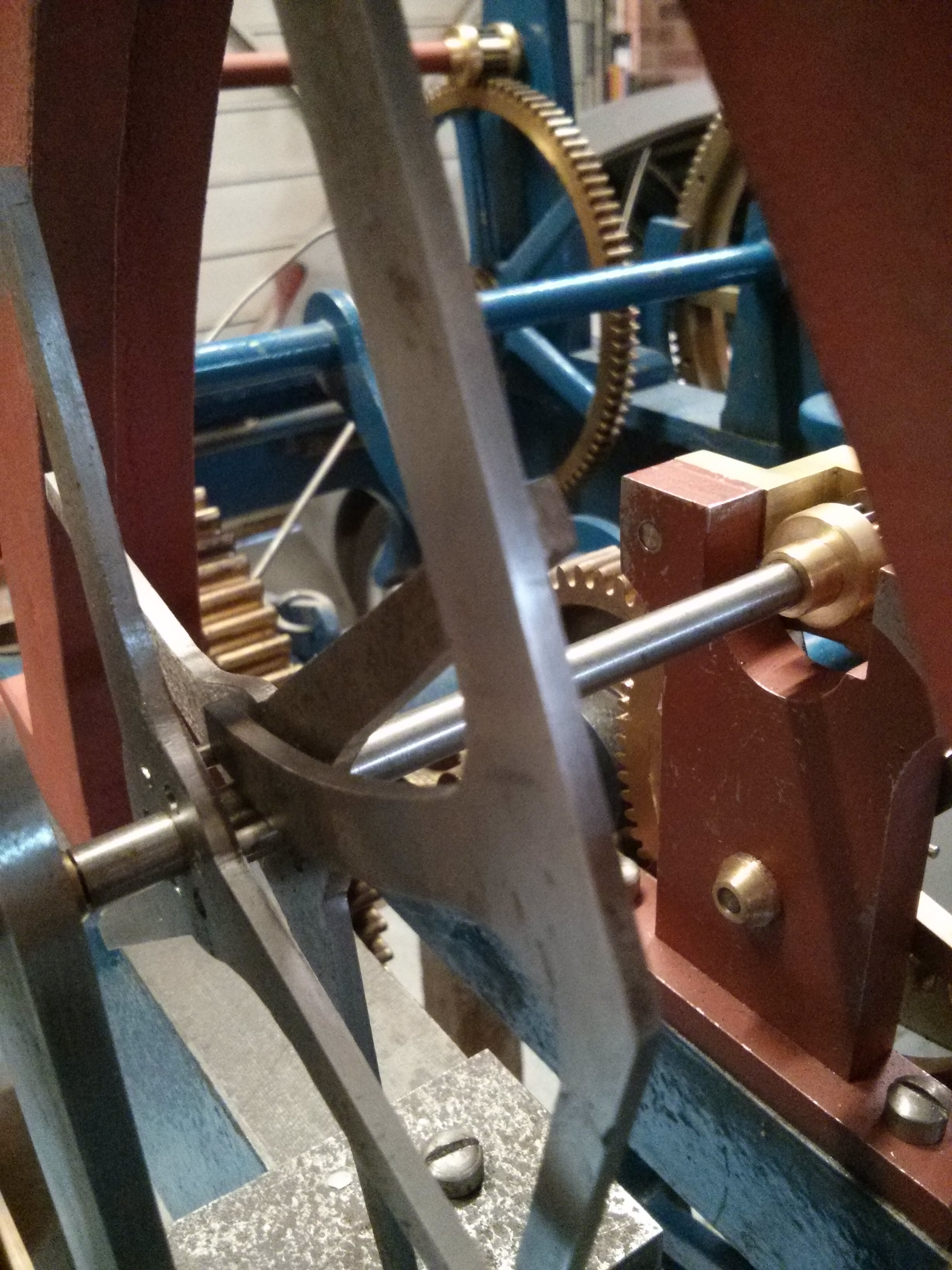
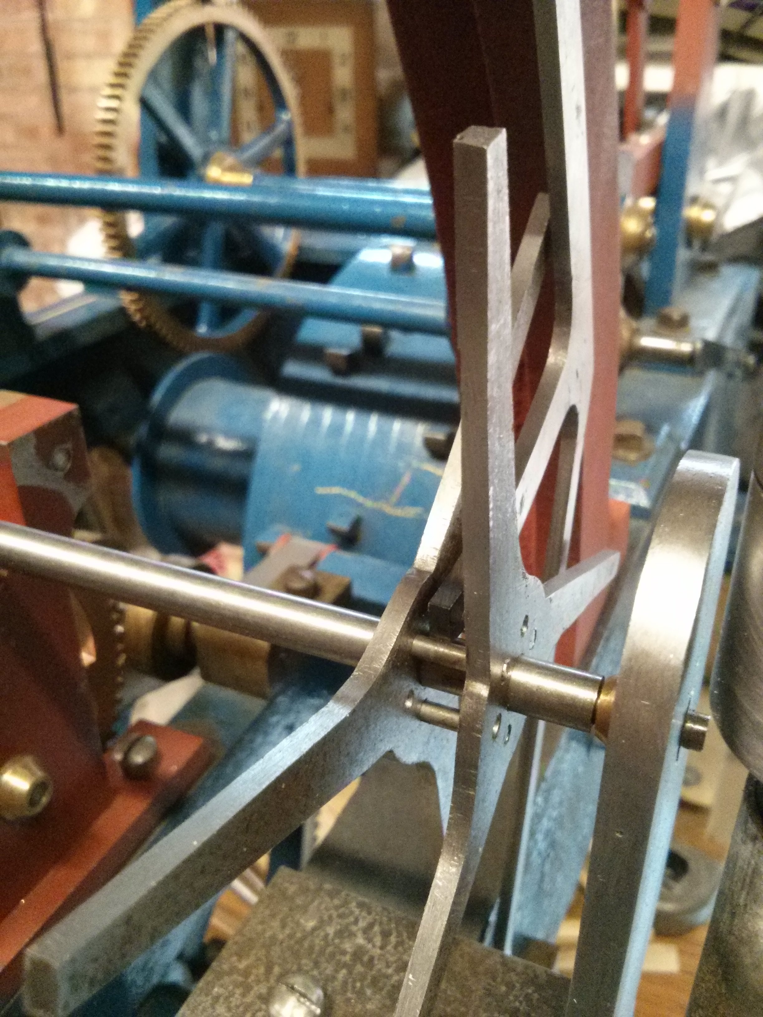
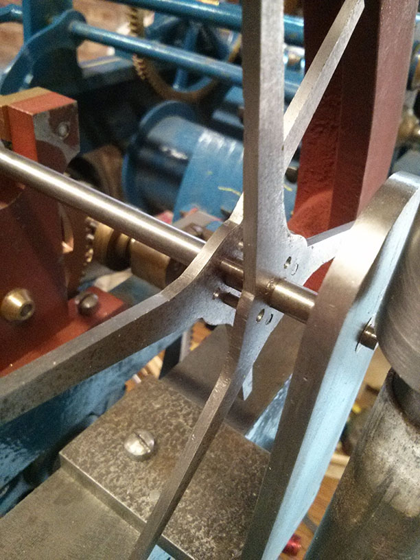
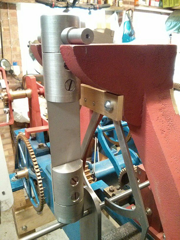
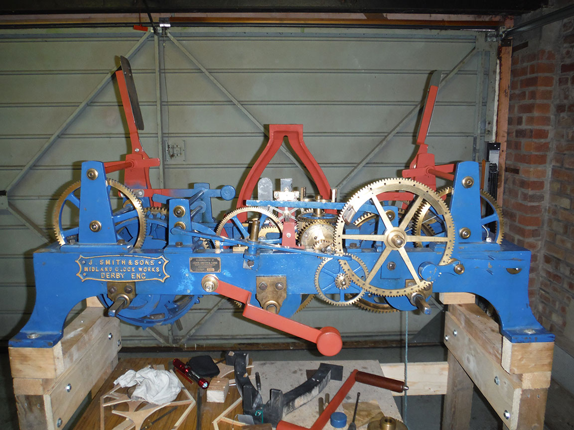
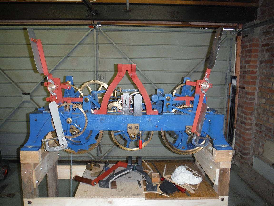
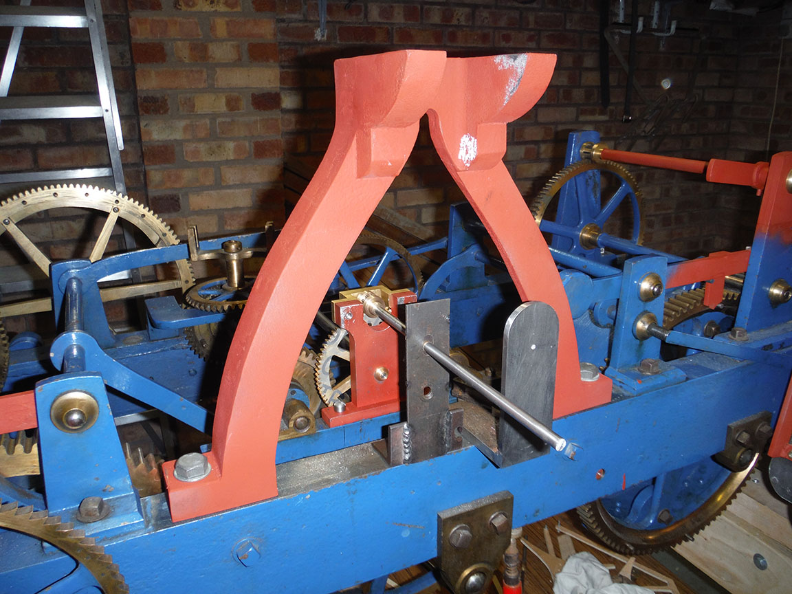
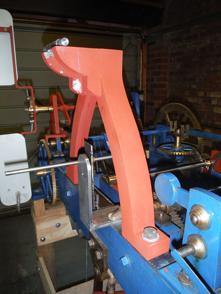
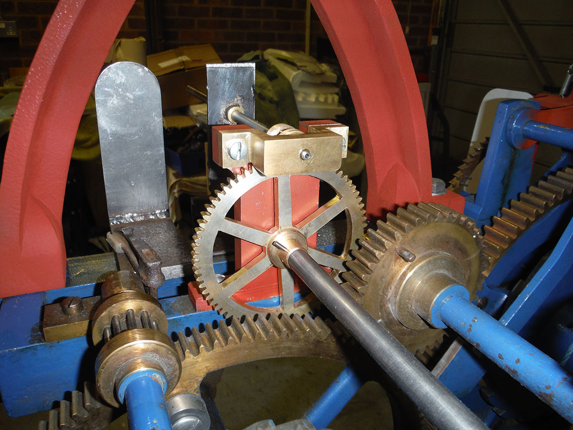
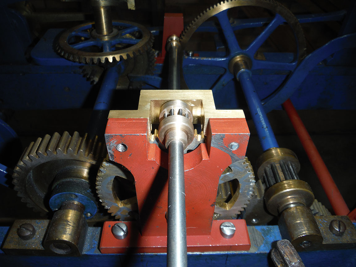
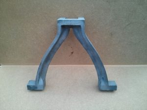
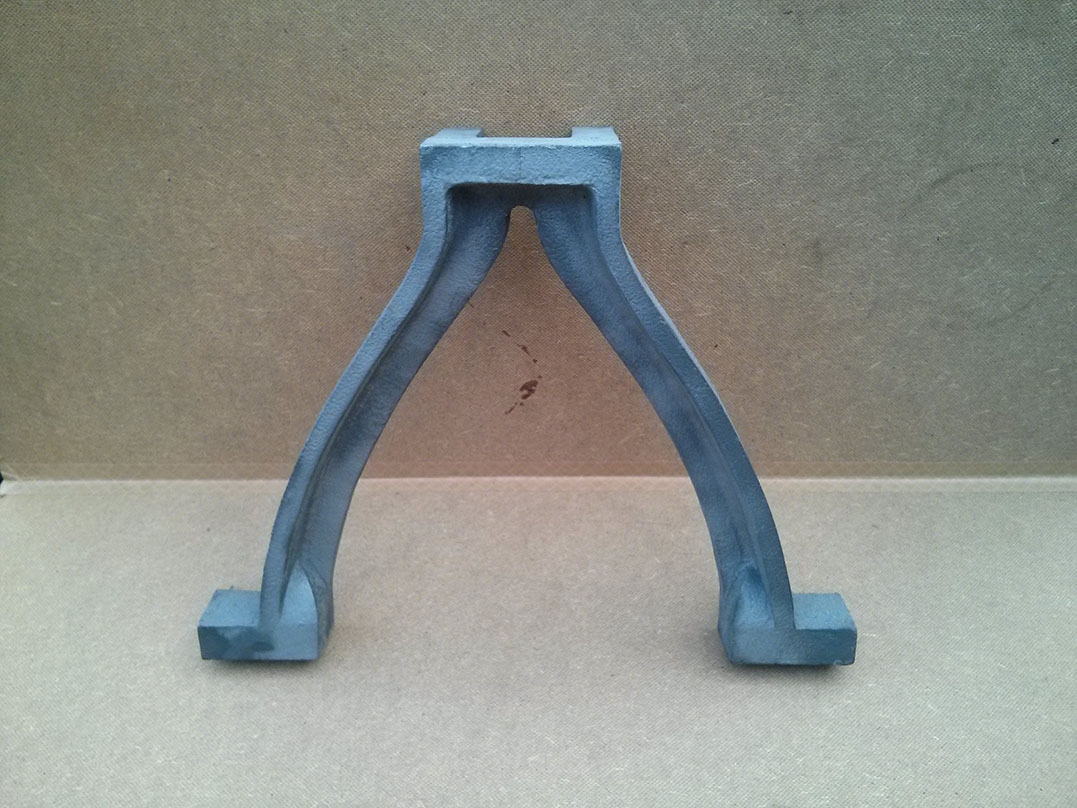
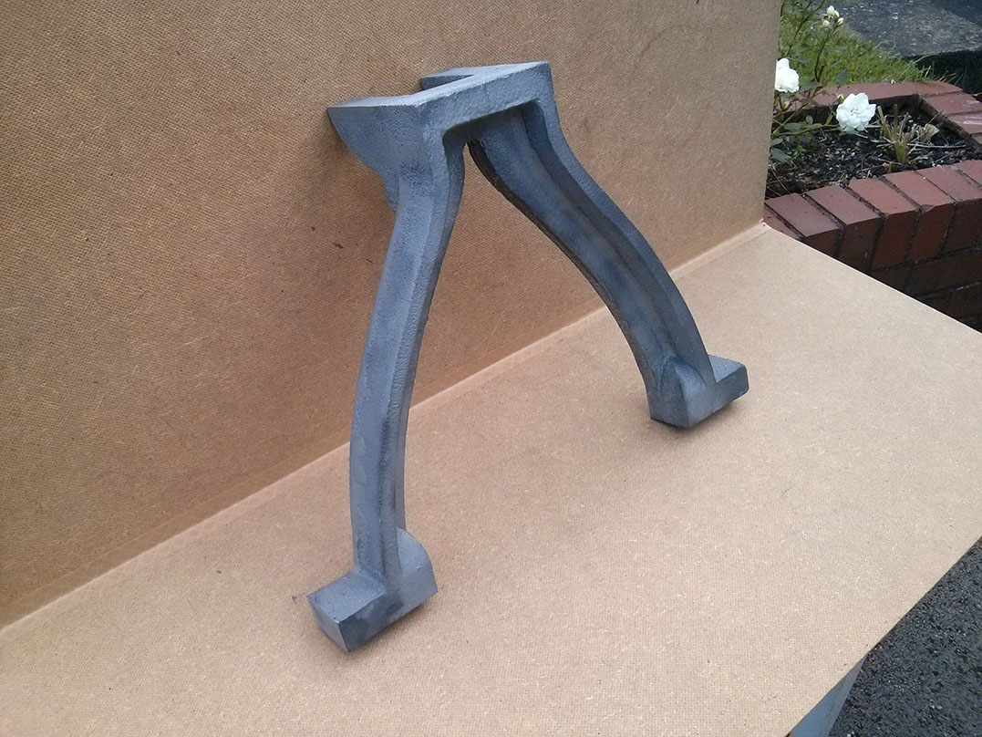
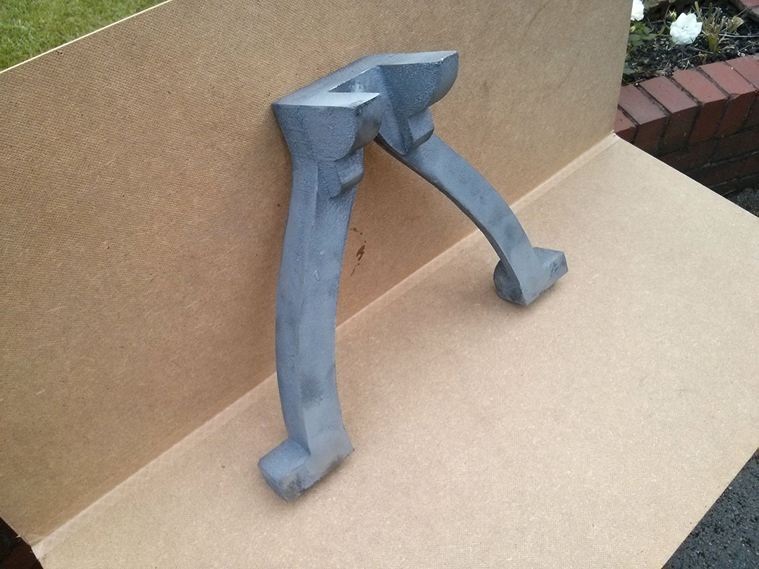
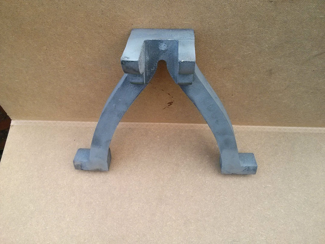
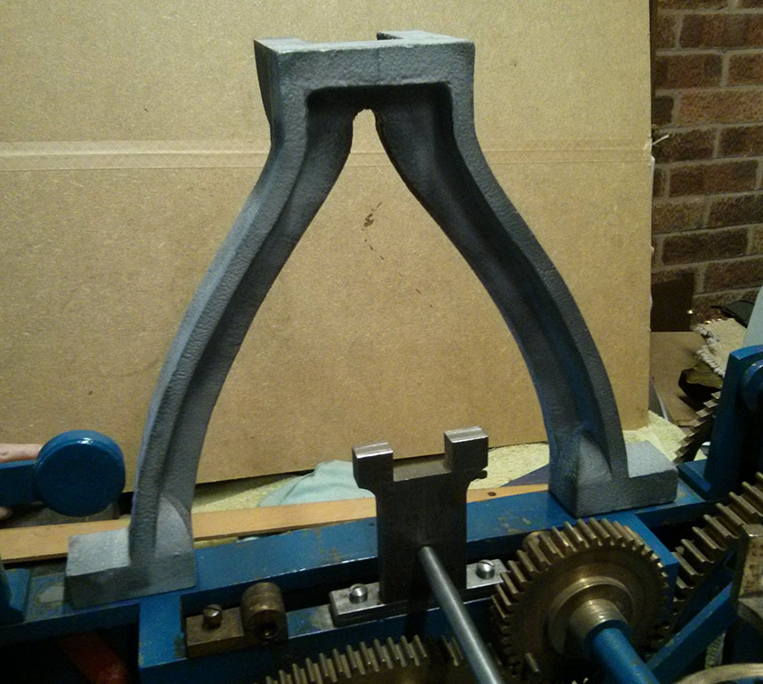
The escapement works – it’s alive! The escapement has been installed and the lifting arms trimmed to the correct length. According to the books we’ve read the pendulum should swing 3 degrees (each way), but nowhere does it say what positions the arms should be lifted to before the pendulum reaches them and how much further they should be moved by the pendulum. The more they are lifted by the pendulum the more energy the pendulum will lose on the upswing and so the less of a push, relatively, will be given to the pendulum on the downswing. This was a simple bit of trial and error, positioning our temporary pendulum manually (the arch pattern was helpful for holding the pendulum, see the pictures below) and seeing where the arm rests on the block and how much the block moves with the rest of the swing. The result we were happy with was lifting the arms to a position reached with the pendulum at 2.5 degrees. This let the arm of the escapement sit about about a third of the way on to the block. When the pendulum pushes the arm the rest of the way to 3 degrees it moves the block enough to unlock the escape wheel with a reasonable looking clearance.

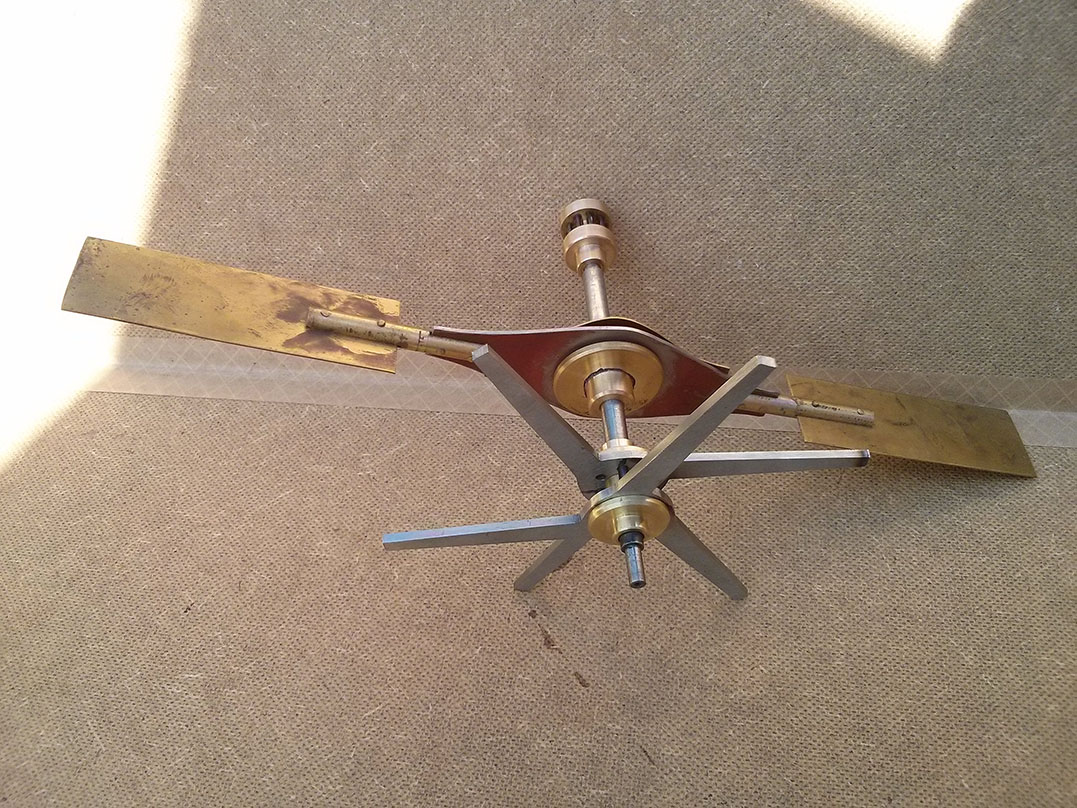
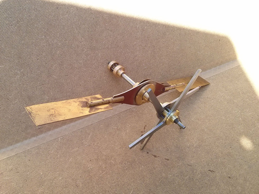
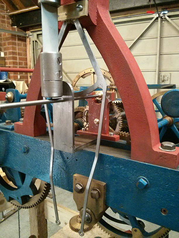
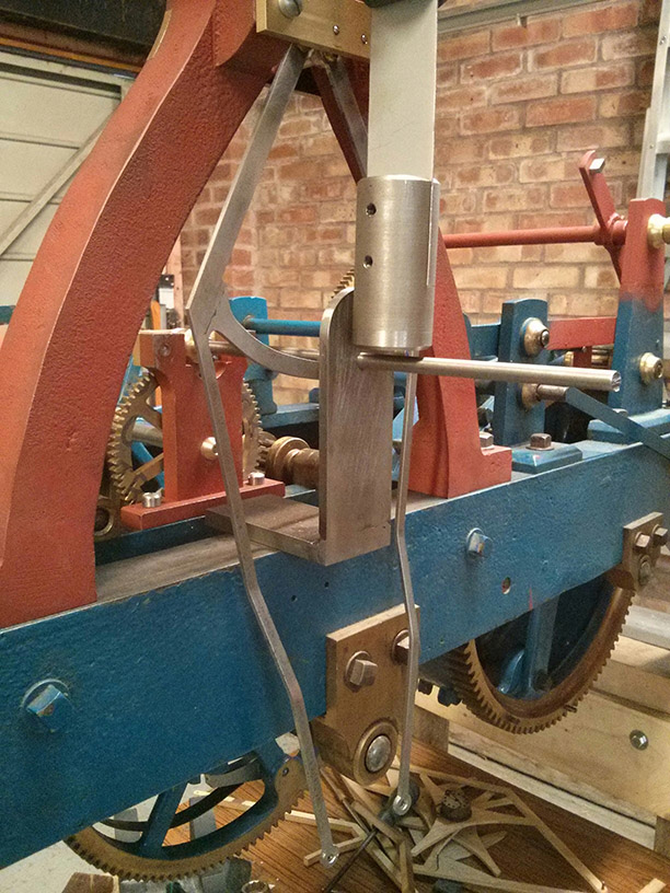
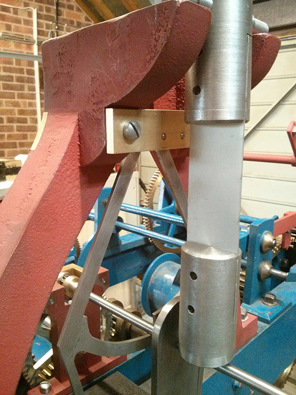
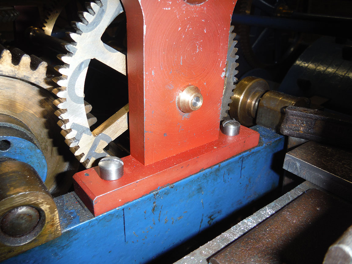
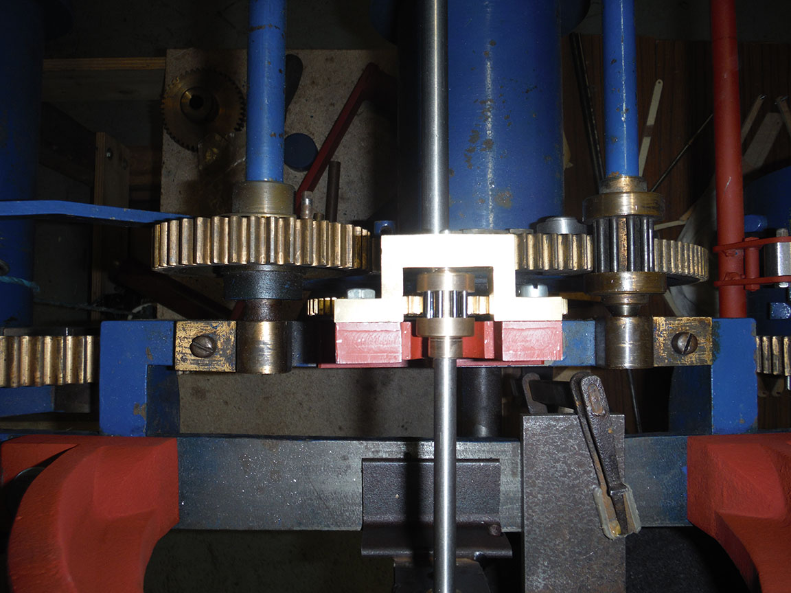
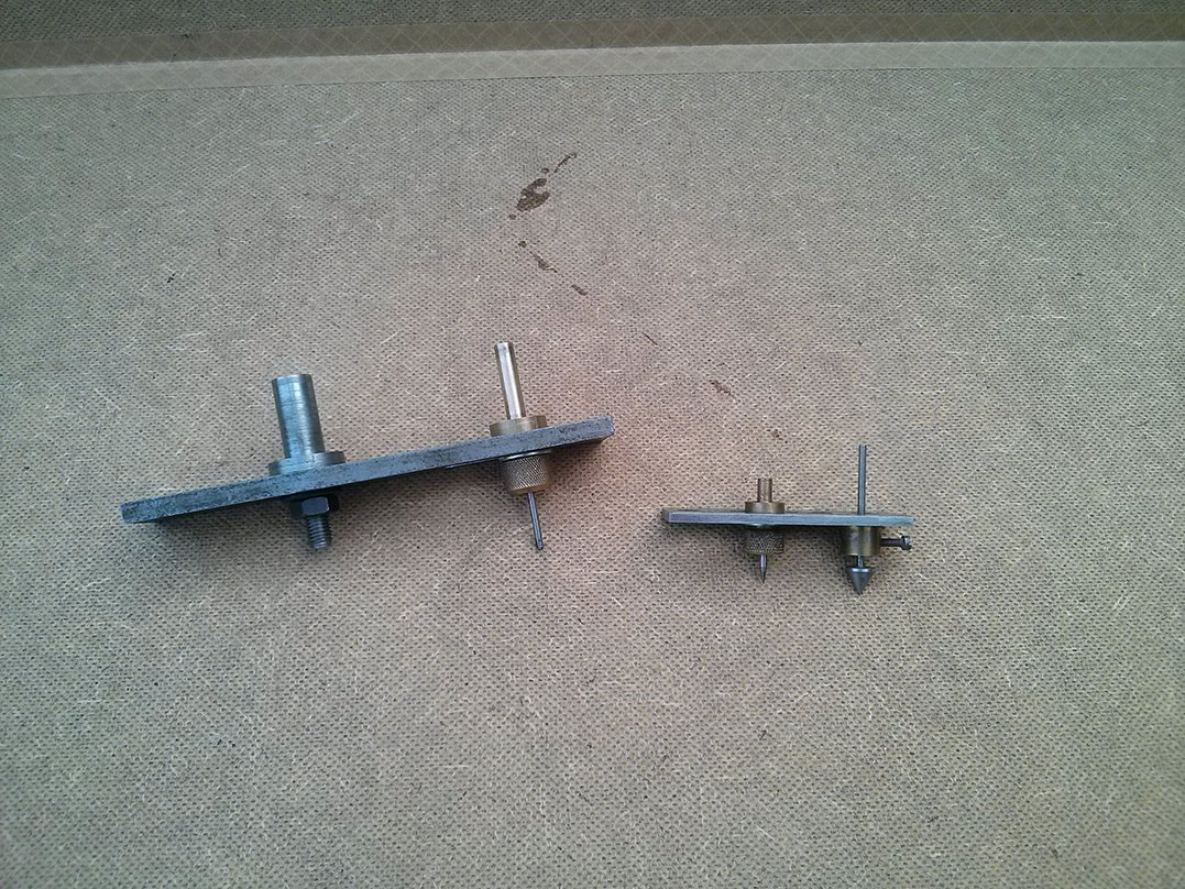
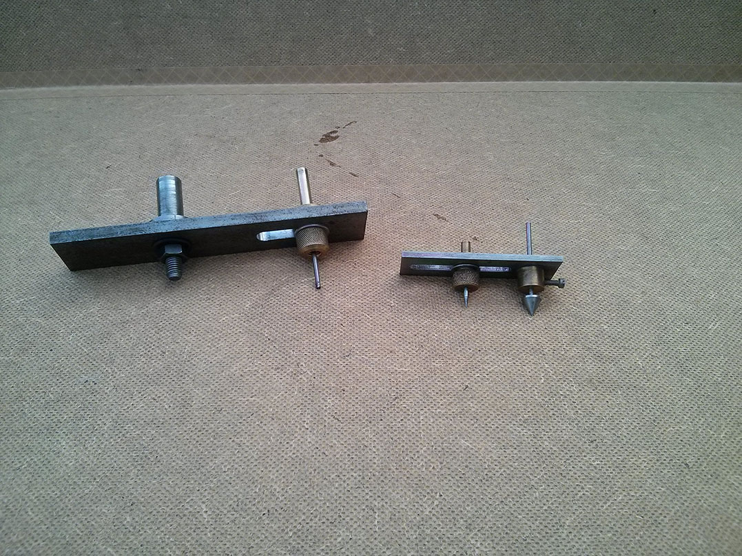
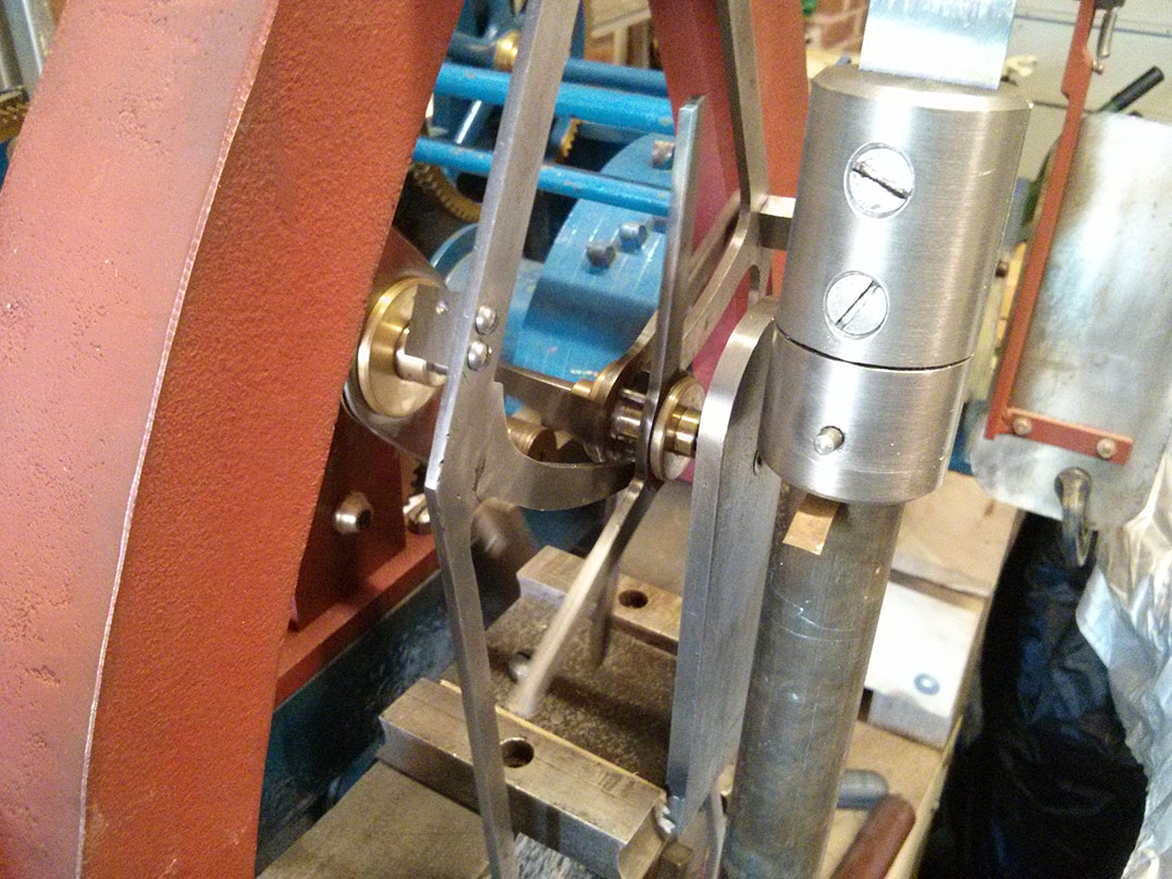
I have uploaded two videos to YouTube showing the escapement in action. In the first video the clock would only run for 5-10 minutes at a time. In the second, after all the new parts had bedded in a little it will run for hours. The blocks you see next to the bracket are in place of the banking pins, which haven’t been made yet. There is a extra collar on the pin at the bottom of the left arm because the arm needs a slight tweak to it’s angle. The pendulum is temporary and too short, so the clock is running faster than it should.

Constructing the double three-legged gravity escapement

It’s been a while since my last post about the turret clock restoration project, not least because there wasn’t a lot of progress over the winter. For a long time we were struggling to work out how the double three-legged gravity escapement itself was constructed. Unfortunately, several offers of help with this didn’t come through but we have managed to work something out that that fits the brief. As always there are a number of ways something like this could be done, but we wanted to replicate the original. Visually we have done that so we must be pretty close, but we don’t know how close.

The method we used was to turn down a hexagonal bar to make the arbour, leaving a short hexagonal section on which to mount the two escape wheels. The hexagonal mount gives the wheels good solid attachment to the arbour preventing any rotation as they hit on to the blocks and stop moving. We can see no way that they could have been pinned to a round arbour and we didn’t think silver soldering them would be sufficient due to the repeated blows they must endure. A small section of brass tube fits over the hexagonal section between the two wheels to keep them the correct distance apart. The three lifting pins are installed between the two wheels in simple holes straight through. A boss fits on either side to sandwich the wheels and tube together and keep then in place, as well as covering the pin holes to keep the pins in. The bosses could be pinned to the arbour, but they don’t appear to be on the original. The arbour isn’t a large diameter and the bosses don’t have a lot of depth to take a pin. As they only need to hold the parts of the escape wheel together, they don’t take any force, we decided to silver solder them on to the arbour. Overall we think our construction technique must be pretty close to that used on the original, but it’s hard to inspect this part on a working clock – our reference clock is viewed from eight feet up a ladder, with the escapement at the back and everything is moving.

Gravity arms for the double three-legged gravity escapement

Gravity arms

This is a quick first look at the gravity arms for the escapement. Unfortunately we have no direct plans for these arms, although the principal is explained in a number of book that we have along with generic designs. We also have limited access to another Smith clock with one, but the people of Duffield would probably not appreciate it if we stopped the clock and dismantled it to scribe around its parts. As a result these have been made from a combination of reference books, awkwardly taken part-measurements and careful study of our own photographs.

I’m not going to include any technical details yet because we don’t know if they will work! We hope this won’t become a process of trial and error but there might be some fine tuning to be done at least. I’ll post more pictures of our progress and details of any problems we find as we continue. Once we have it working I will, of course, provide proper details. These arms have been made from multiple parts welded together which I don’t imagine is how the originals were done, presumably they were cut from a single piece. However, this technique has made them a lot quicker and easier to produce (important since we might have to make more variations yet, if they don’t work) and the results look fine. Even easier would have been getting access to a water-jet cutter, then we could have just drawn them up on the computer and a few minutes later had a perfect set pop out of the machine.

Pendulum suspension

Pendulum suspension

A quick post to show the new pendulum suspension. This is a departure from the square version on the St. Alkmund’s church clock, but it’s been made to plans from Smith of Derby so it is an authentic design (if only we had plans for some of the more complicated bits, like the escapement!). There’s no way of knowing which design this clock would have had originally, so I’d be happy with either.

It’s surprising just how heavy this bit is, but it’s nothing compared to the weight of the whole pendulum. In actual fact we don’t know what the pendulum bob should weigh, but it’s a fair estimate to say it’ll weigh quite a bit. I really hope the new casting was well made, because all that weight is going to be hanging off it!

The current bolts are temporary ones and that is not spring steel connecting the two parts yet – we’re having trouble tacking down a source of suitably sized spring steel strip (at a sensible price). You will also notice gravity arms have been added, as well as the brass plates that hold them, but more on that in another post.

Escapement fly

Escapement fly, back view.

The double three-legged gravity escapement uses a fly to dissipate some of the excess energy in the system. When the escapement unlocks the legs of the escapement move 60 degrees before coming to a sudden stop again. The fly helps to reduce the acceleration of the escape wheel and, like the fly on the striking train, needs to be able to continue to move a little when the arbour stops suddenly. Unlike the bigger fly this one doesn’t use a ratchet, instead it uses a friction device. We need enough friction that it gets turned with the arbour starts to move, but when the arbour stops it should be able to slip and come to a natural stop. The fly was made from a drawing supplied by Smith of Derby when my Father visited them. It’s no coincidence that it looks just like the one on the St. Alkmund’s church clock.

The pictures below show the completed fly, with a bolt through the middle where the arbour would normally be – which is why it looks a little wonky in some of the pictures.

Turret clock restoration progress report

DSCF3706

I thought a progress report was in order for the turret clock we (my father and I) are restoring, after I realised we started this project way back in November 2014! As a refresher the clock is a 1922 cast iron flat bed turret clock made by John Smith & Sons of Derby. It was purchased in a poor state of repair, having been butchered in the 1950s to make it electric drive and later having much of the electrics stripped back off. The original parts removed during the motorisation would have been recycled at the time so were no longer available to be replaced, later removal of the motors (etc.) just left the clock in a non-working state.

Since November 2014 a lot has been achieved. We now have fully working striking and chiming trains and the going train finally feels like it’s well on its way to completion. I’ve tried to list out everything that has been made or sorted so far. Pictures of the current state of the clock are below, along with some pictures showing details of recent additions to the going train. The red parts are all new, as are quite a lot of brass parts and several steel arbours which haven’t been painted. Eventually the clock will be properly painted but in the mean time the red primer makes a nice contrast between the new and original parts. There are a few temporary supports and bolts in the pictures, but this is still very much work-in-progress.

Striking & chiming trains

Going train

Other

  • Removed 1974 plaque (covered maintaining power hole) and patched bolt holes
  • New maintaining power – arbour, front bush, pushing mechanism, arm and weight
  • New winding handle

Our first bell

bell-ebay-2

I’m already resigned to the fact that I’ll never own the set of 8 full size church bells intended for the chiming train. However, I do now have one so the clock will at least be able to strike the hour. This is a proper bell too, exactly like you would find in your local church. Admittedly it’s at the smaller end of the scale but it really looks the part. It was cast by John Taylor & Company Loughborough who, just like Smith of Derby who made the clock, are still going today. I bought the bell a couple of weeks ago from a retired GP near Tamworth via e-Bay. According to the listing it was “probably made around the turn of the 19th/20th century for a school in Norfolk possibly Stoke by Nayland”. It came with a substantial bracket and was intended to be wall mounted and rung by pulling a chain. The bell itself is 12.5 inches in diameter, 13.5 inches high and weighs 56 lbs.

The previous owner of the bell did say that he’d had the bell checked out and that the length of the ringing tone was slightly shorted than it should be and so there could be a crack. It rings well to my ear and there is certainly no visible defect so I’m happy with it. Don’t forget that Big Ben has been cracked pretty ever much since it was installed, mind you Big Ben doesn’t sound particularly good so that’s not saying much. The funny thing here is that before this bell went on eBay the previous owner offered it to UK Architectural Antiques in Staffordshire, but they weren’t interested because of this potential defect. This is the same company from whom I purchased the clock which, it should be fairly clear from this blog, was a long way from being in mint condition!

Positioning a new arbour

IMG_20160621_194002

Now we have our new wheel we need another new lantern pinion to engage with it and that pinion needs to be mounted on another new arbour. The position of the arbour needs to be chosen carefully to ensure a good mesh between wheel and pinion. Our horizontal position is fixed – it needs to sit central to the rest of the escapement position. However, we can choose the vertical position, up to a point, to ensure the correct mesh. The vertical position of the remaining escapement parts (still to be made) will then follow.

To aid the positioning of the arbour Dad made a little tool which can have the wheel and pinion mounted on it allowing the mesh to be perfected, before scribing the arbour position (where it crosses the horizontal midline). I’ve attached pictures showing the tool for this clock and a smaller version he used previously when making a couple of long case clock movements. The new tool (that’s the bigger one, in case you hadn’t guessed) isn’t quite finished as you can see compared to the original. From the pictures you can see how the mesh is adjusted with the wheel and pinion mounted on the tool. Then the tool’s wheel arbour can be placed in the bearing on the clock and the tool rotated to see where the pinion’s arbour crosses the horizontal midline and the position scribed.

Cutting a new wheel

Test cut wheels in plastic and brass.

So far we have needed to create several new lantern pinions but no wheels, until now. The next missing part of the going train is a wheel and we have already worked out how many teeth it needs (72 based on a 1.25 second swing of the pendulum). Based on the 72 teeth, and the dimensions of the arch made based on measurements from St. Alkmund’s clock, we ended up with a diameter of 4.522 inches. The pitch circle diameter of the 9 pin pinion it engages with is 0.478 inches.

Cutting the wheel should be easy in theory, with a milling machine and a dividing head, although finding the right cutter isn’t. These wheels should have epicycloidal teeth of a decent depth, to engage with a lantern pinion, but you just can’t seem to get suitable cutters any more. One option would have been to make a fly cutter, but we managed to avoid the need to do that. A test wheel cut with involute teeth and deepened slots seemed to work pretty well so we decided to go with that. The first test was cut in a bit of plastic fascia board, then a section was to be test cut in brass on a blank made from an old engraved sign. Dad got a bit carried away and cut the entire thing and after spending so many hours on it we decided to keep it, despite the remnants of engraved lettering on one side, at least for the time being. After the cut-outs to form the spokes there won’t be a lot of the lettering left and a little metal filler, maybe even a touch of brass coloured paint, and the last traces will disappear. If not we can always replace it later, but in the mean time we can move on to the next part.

The dividing head was from my Dad’s Myford ML7, but was set up on an unbranded ‘Micro Mill’ because it gave a better view at the point of cutting.

Freshly cast pendulum support

Newly cast pendulum support.

The pendulum support has been cast and we’ve just got it back from the foundry. It’s not quite finished yet though. It needs a bit of light sanding to remove some of the casting marks on the edges. Then it needs the bottom of the two feet flattening so it sits nicely on the clock’s frame, plus bolt holes drilling. Recessed areas needs to be milled to mount brass plates on the front and back. Finally, a v-shaped groove needs to be cut across the top for a small bar to sit in,  from which the pendulum actually hangs. This is another significant chunk (literally) of the clock done, or almost done, and allows further progress to be made on building the new escapement.