The slightly different striking control

Strike control mechanism - lifting projection

We assumed the striking and chiming control mechanisms were the same, however we found a subtle but important difference. At first we were unable to get the mechanism to run correctly. It just didn’t work from any obvious starting point of the two pin pinion.

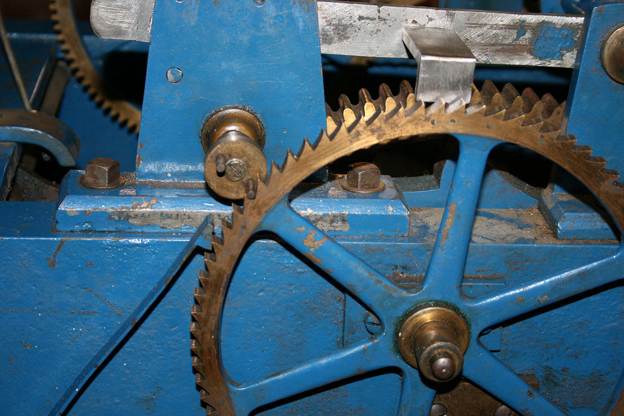
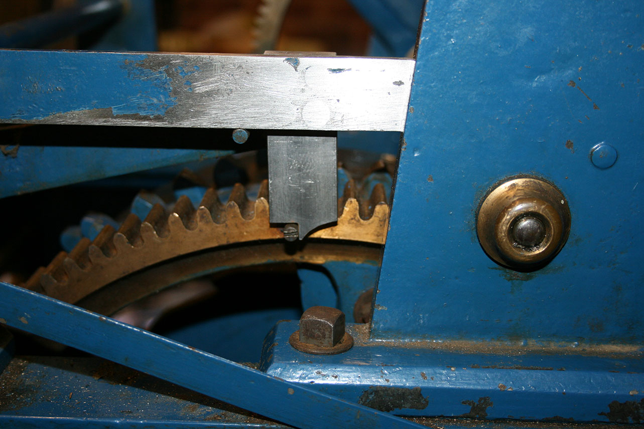
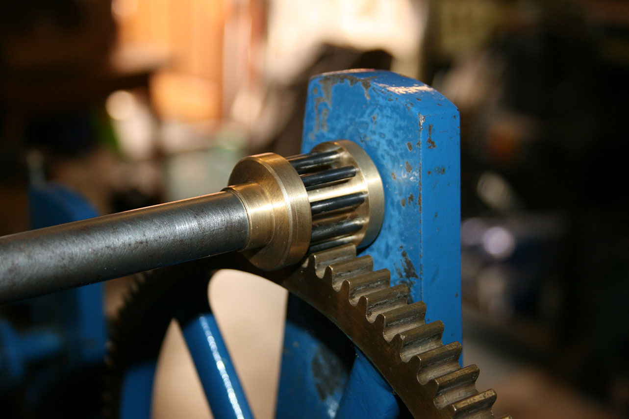
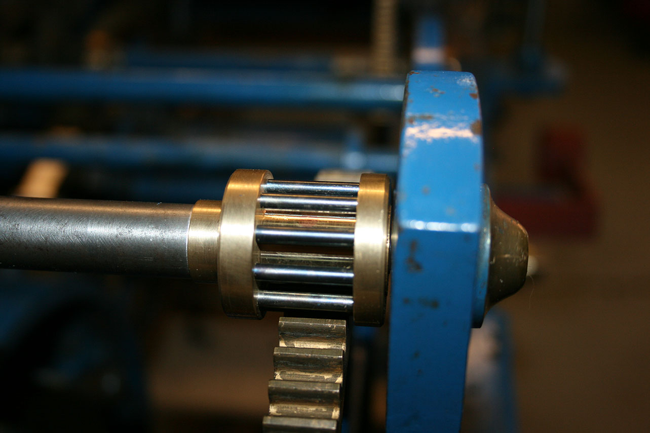
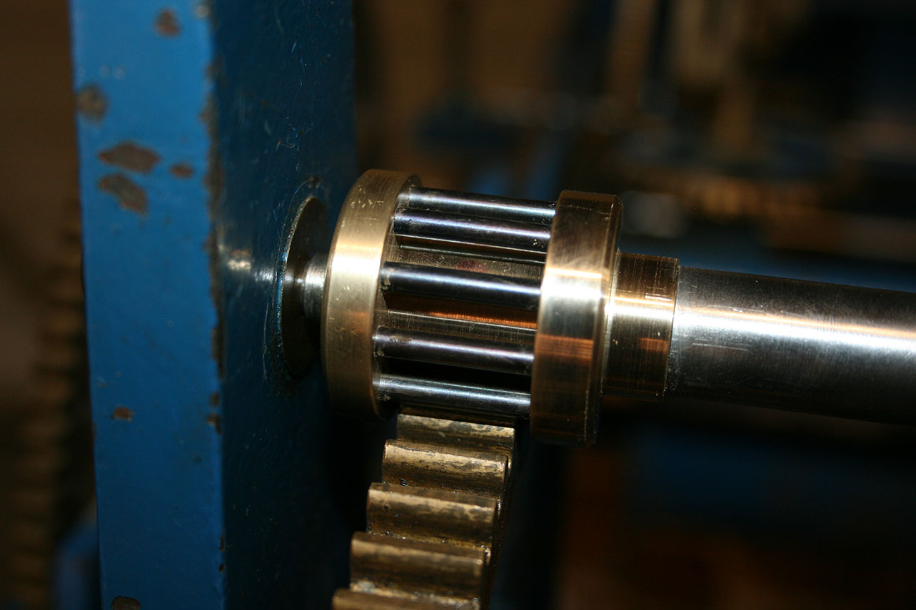
The significance of the two pin pinion is that the ratchet wheel does not move in a continuous manner but rather in steps (two per revolution of the arbour). The equivalent wheel on the chiming train moves continuously.

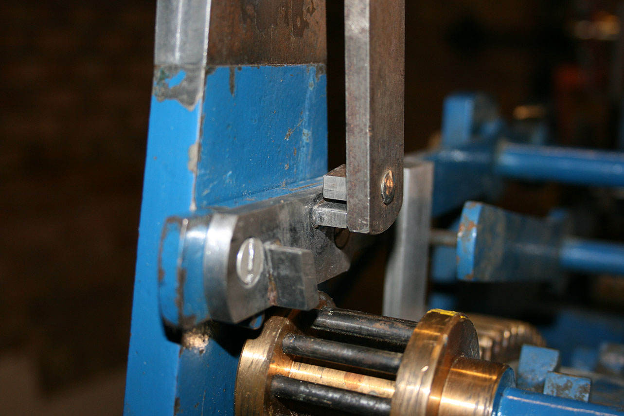
This is important because the ratchet wheel, which contains the lifting pin, must move at the start of the striking process (to allow the horizontal arm to drop) and at the end (to lift the arm back up). For the striking train it moves one step per hour being struck. Considering the striking of one o’clock, where the ratchet wheel only moves one tooth, it is clear that there must be movement of half a tooth at the start and half a tooth at the end of striking. That means the rest position of the ratchet wheel must be mid-movement, so the spring pawl cannot sit in a fully engaged position at rest, it needs to sit half way between teeth. This doesn’t seem like a natural resting position, but it does work. When at rest one of the pins is engaged with the ratchet wheel and when the pin comes out of mesh the pawl is engaged. The result is that either a pin or the pawl is always engaged with the ratchet wheel to prevent it moving inappropriately.

The fly arbour rotates five times per tooth of the ratchet wheel / strike of the bell.

To strike one o’clock:

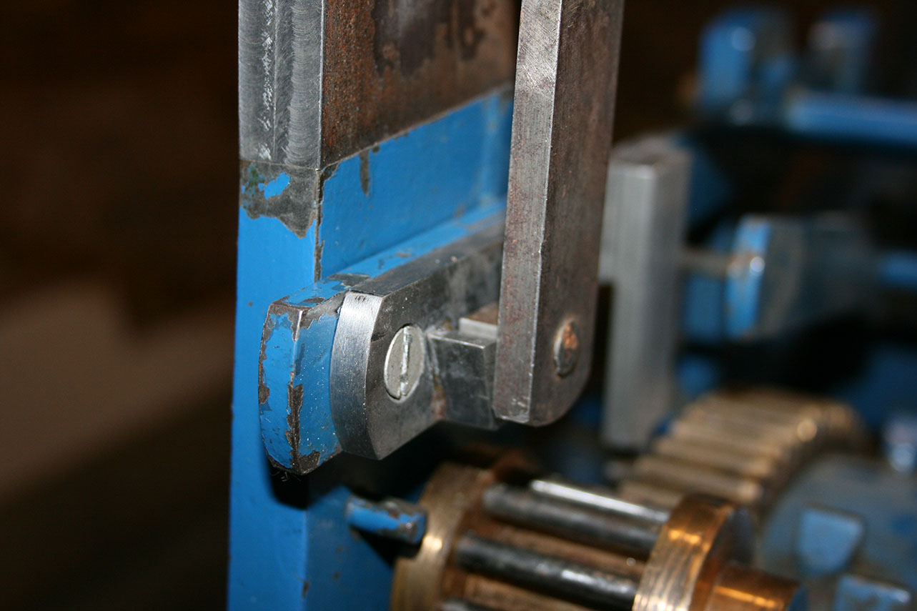
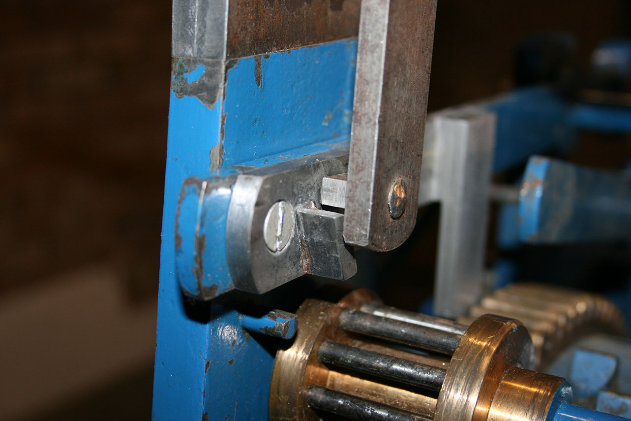
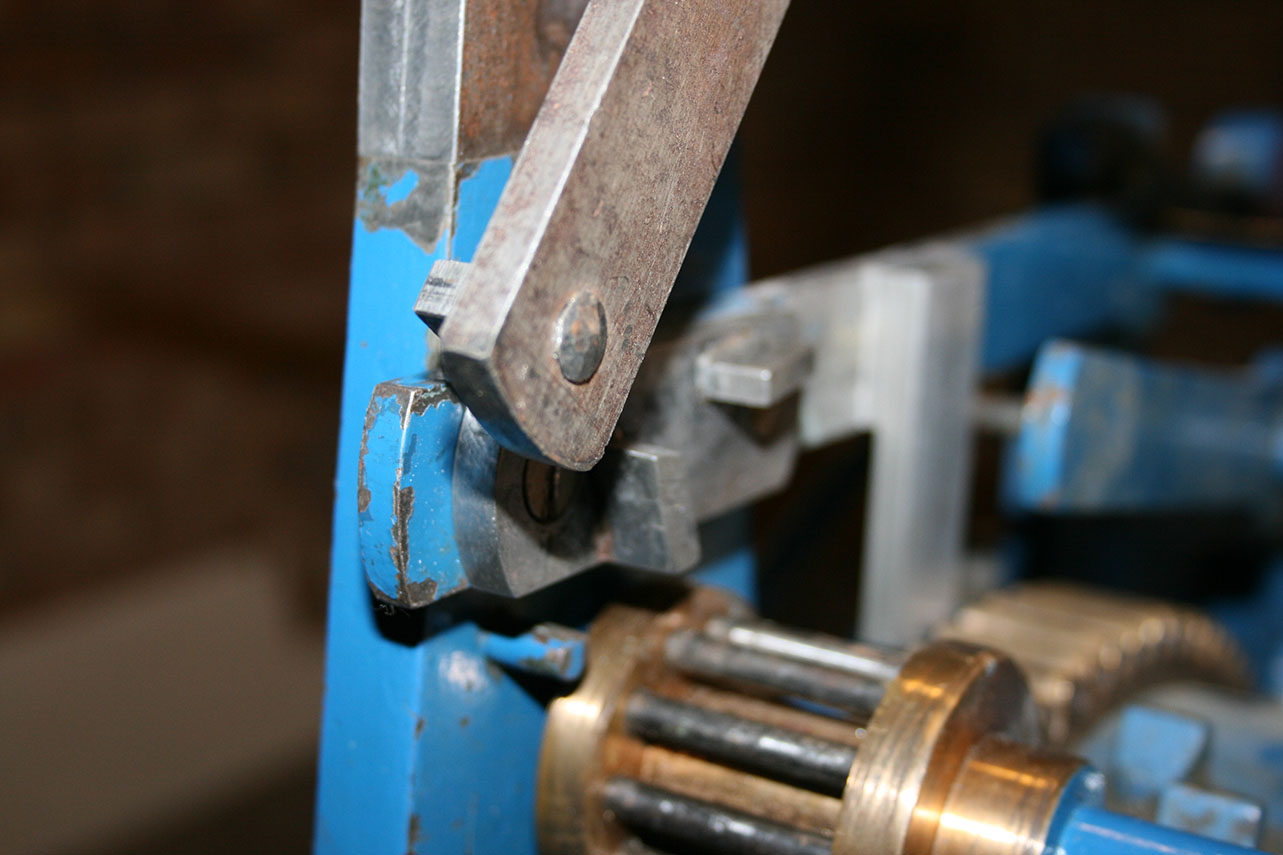
  • The first rotation of the fly arbour moves the ratchet wheel half a tooth, the two pin pinion disengages from the ratchet wheel and the spring pawl engages. This movement is enough for the horizontal arm to drop off the lifting pin on the ratchet wheel.
  • The fly arbour then rotates freely for four turns, the two pin pinion remains out of mesh with the ratchet wheel.
  • In the final half rotation the second pin in the pinion engages with the ratchet wheel and moves it half a turn. This causes the lifting pin to raise the horizontal arm and stop the striking mechanism.
  • The rest of the mechanism works just like the chiming mechanism.

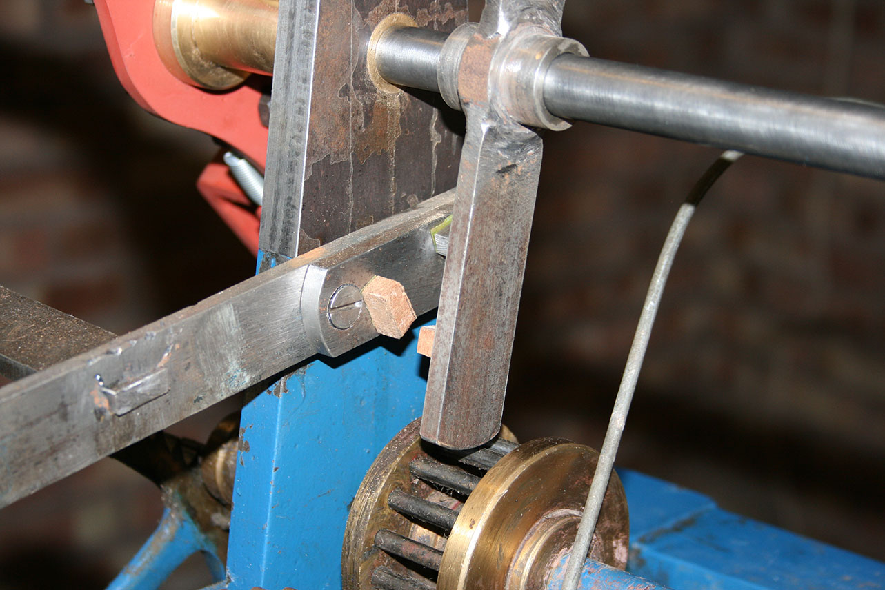
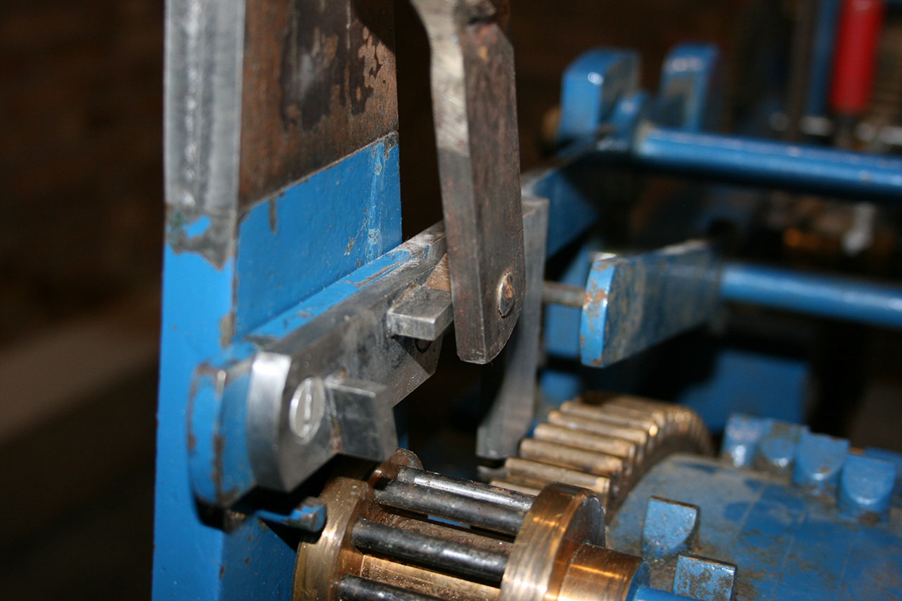
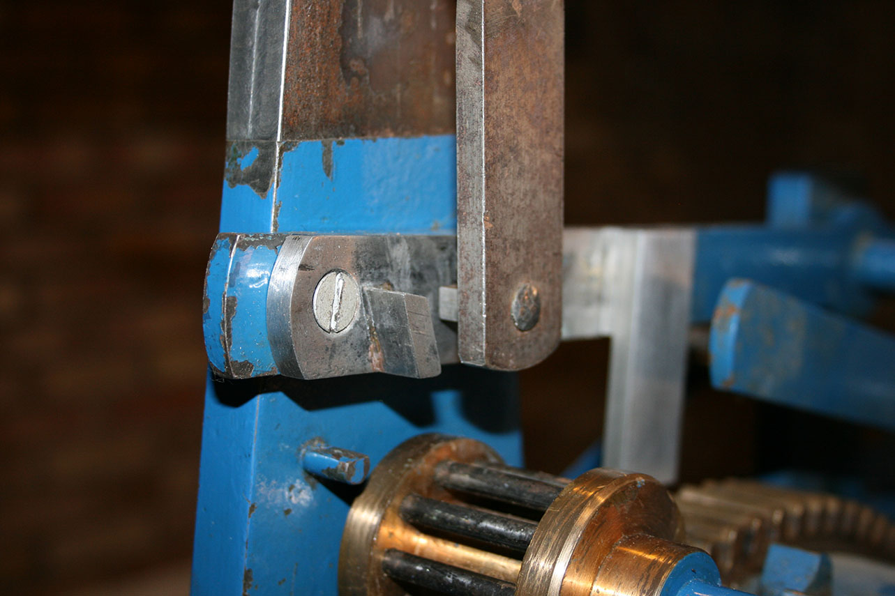
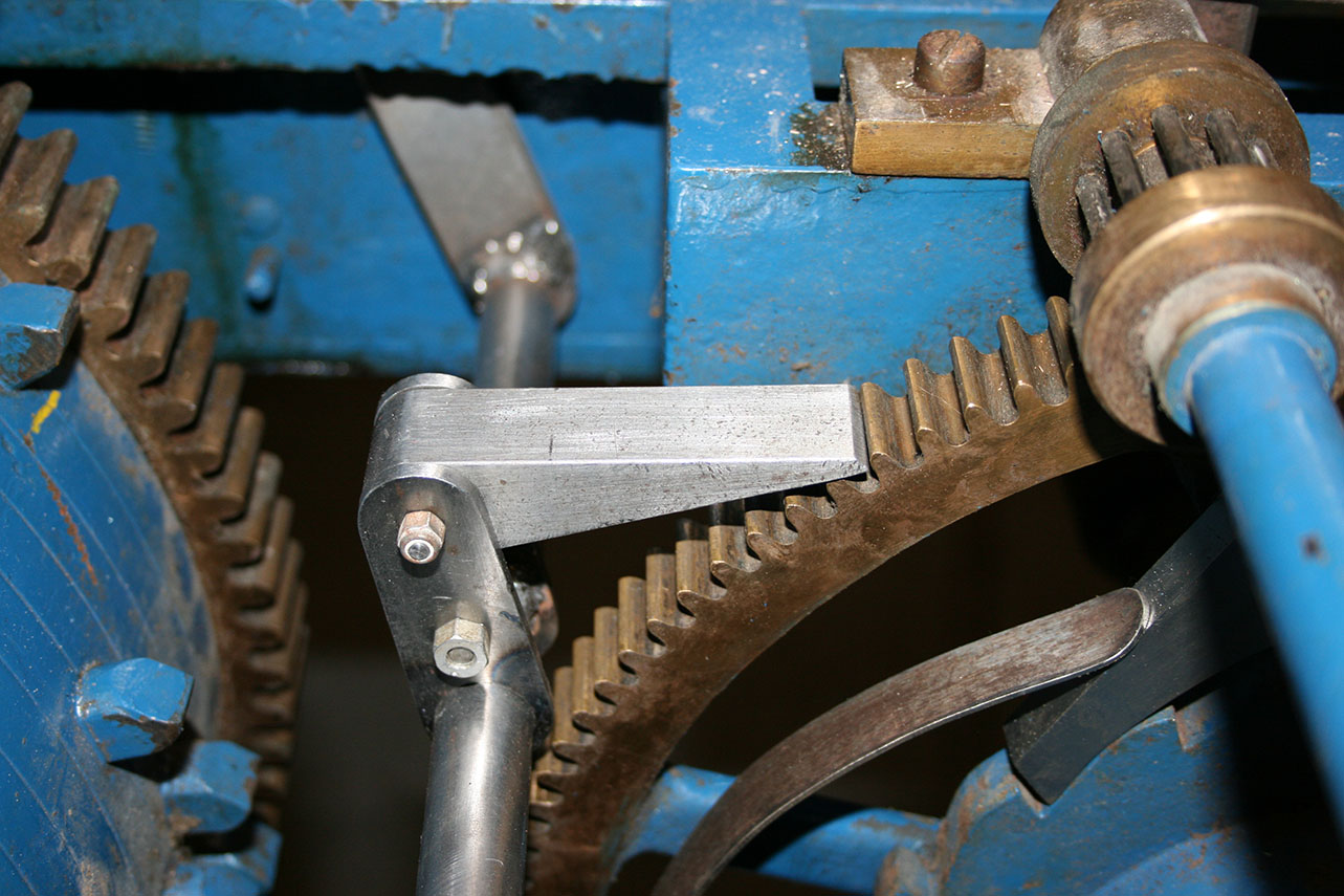
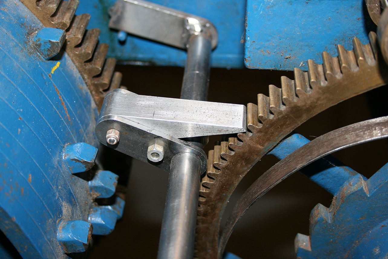
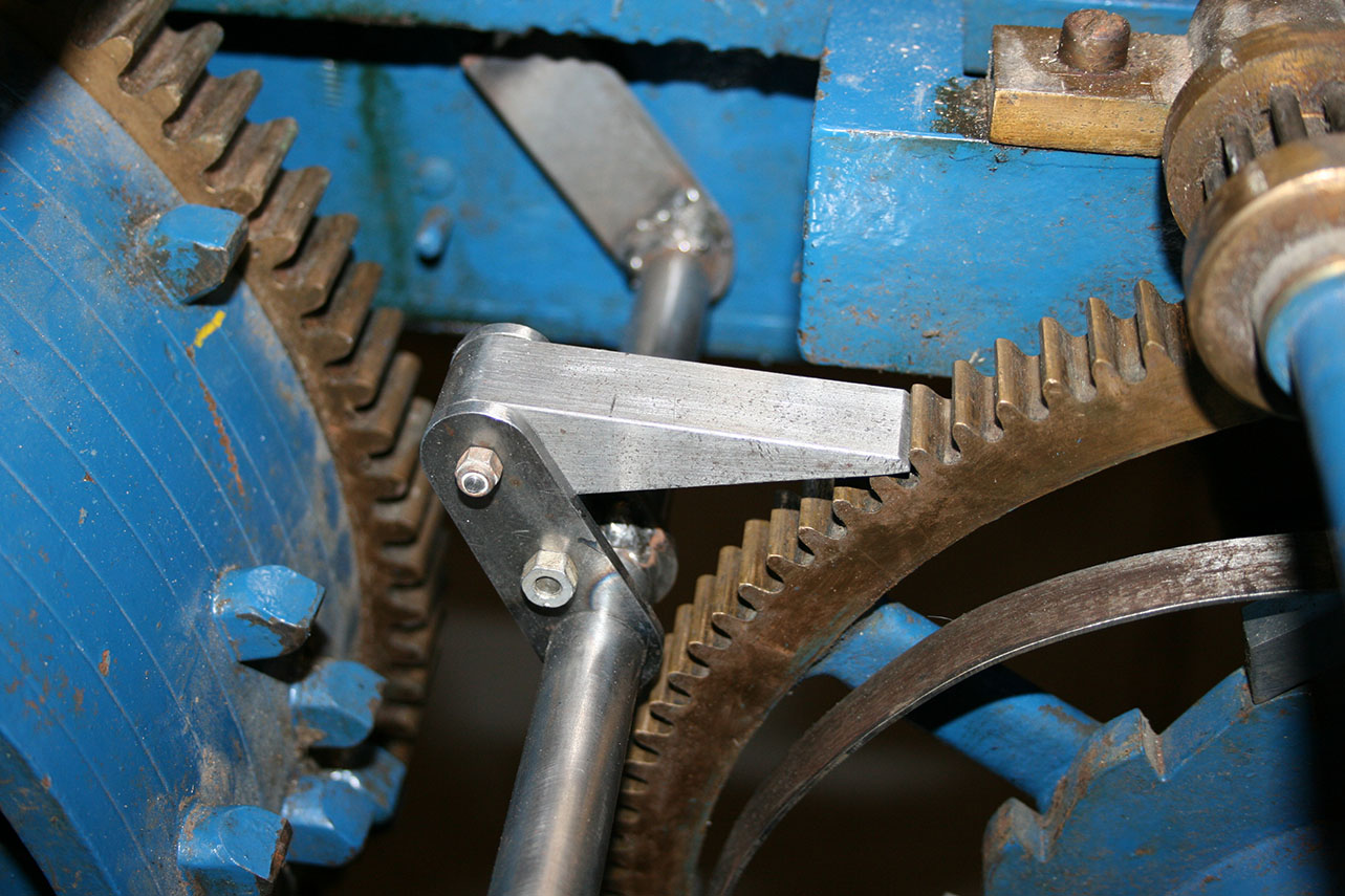
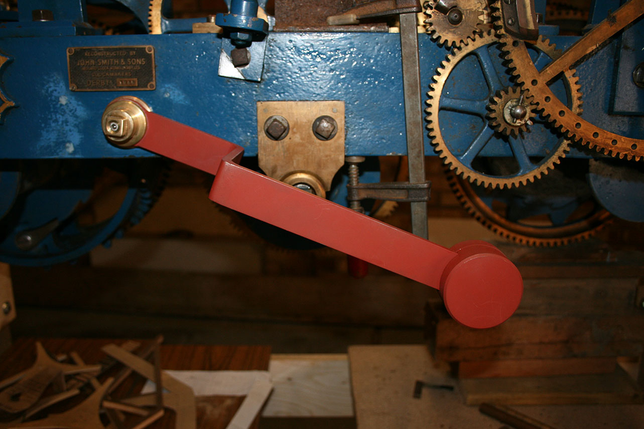
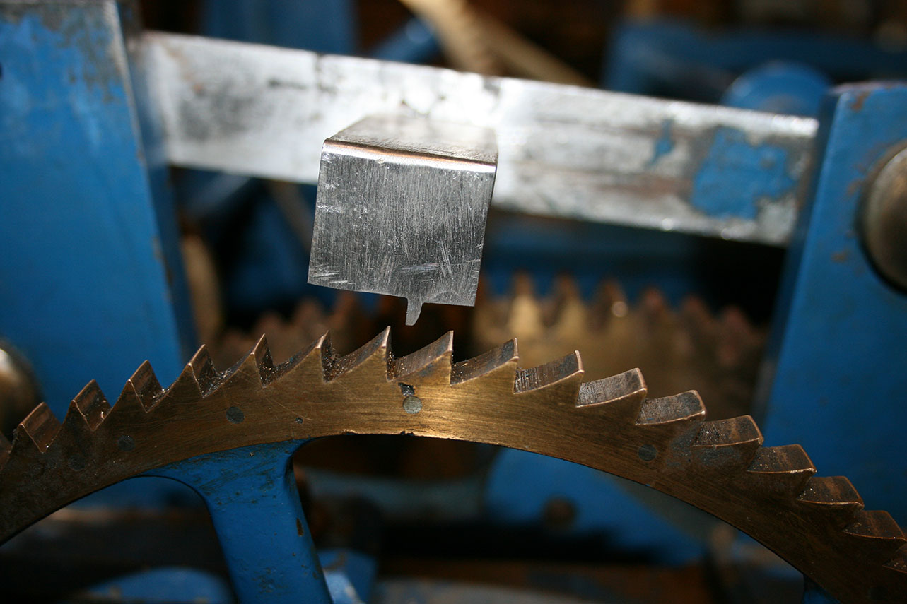
The lifting projection has to be very slim so it isn’t able to accommodate much of a ramp – the pictured projection doesn’t look like it would work but it does, in fact it works very well. Note the pictures showing the resting positions of the ratchet wheel, pawl and two pin pinion. There is also a picture showing how the positions of the blocks were prototyped in wood (attached with double sided tape).

Completed chime control mechanism

Finished chime control mechanism

The control mechanism for the chiming train is now complete (all but for pinning the rotating arm to the fly arbour). Read the previous two posts on this mechanism for background.

I’ll repeat the explanation (improved and modified slightly) from the earlier post of how the process works, with pictures of the finished product.

Starting position before chiming

Chime control mechanism - raised on stopping pin

The horizontal arm is held just above the rest pin. It is held there by the downward projection from the arm which has been lifted onto one of the four pins around the large wheel attached to the barrel.

Chime control mechanism - locked position

The rotating arm on the fly arbour is always trying to rotate clockwise but is obstructed because the square block projecting from it is locked against the square block projecting from the catch plate. Note the horizontal arm is above the rest pin.

Chiming process

Chime control mechanism - first stage of unlocking

The horizontal arm is lifted (note the increased gap between the rest pin and the arm) briefly by the going train, on each quarter hour. This unlocks the rotating arm, attached to the fly arbour so its projecting block can pass below the block on the catch plate.

Chime control mechanism - temporary locking stage

The projecting block of the rotating arm now briefly locks against the upright (angled) block on the catch plate, awaiting its final release.

Chime control mechanism - final release

The lifting mechanism from the going train disengages, causing the horizontal arm to drop back to it’s starting position (still above the rest pin). This unlocks the rotating arm again and allows the projecting block on the arm to pass over the upright block.

Chime control mechanism - starting to rotate

The fly arbour begins to rotate, which means the rest of the striking train moves too.

Chime control mechanism - off the lifting pin

About half way through the first rotation of the fly arbour the large wheel on the barrel has rotated far enough that the downward projection from the horizontal arm drops off the pin.

Chime control mechanism - rotating freely

The horizontal arm drops down, below it’s starting point, and finally rests on the rest pin. This allows the rotating arm to rotate freely, it’s projecting block passing over the horizontal block on the catch plate.

Chime control mechanism - raised on stopping pin

When the chime barrel reaches the end of the tune, the next pin on the wheel reaches the point where it raises the horizontal arm.

Chime control mechanism - locked position

The block on the rotating arm now collides with the horizontal block on the catch plate causing the arbour, and rest of the train, to stop abruptly (except the fly, which is able to come to  rest gradually thanks to its ratchet drive).

Completed fly arbour pinions

Completed fly arbour lantern  pinion, angled view

The completion of the flies meant the lantern pinions could be attached to the fly arbours. They are now pinned though the centre section, just like the originals, and the pins have been machined perfectly smooth with the pinion body.

The pins have been cut to length and hardened. Then the brass end cap was attached – a simple tight push fit. The end cap has then been machined to a perfect match with the body and a little bevel put on, which helps to mask any visible line at the join.

Compare the pictures of the two new pinions with one of the originals when I originally discussed their construction. Note the bronze dot just visible between the trundles where it is pinned to the arbour.


Completed maintaining power

Maintaining power pawl, riding over teeth of great wheel.

The maintaining power is now completely finished. The lever has a weight. The pawl to advance the great wheel has been made and attached (welded to the arbour). There is even a stop to prevent the lever being lifted too high and to prevent it dropping below the level of the winding peg.

From the fully charged position (lever all the way up) there is approximately four minutes to wind the going train. It actually takes about six minutes to return to resting position but because it passes in front of the winding peg it would rest on the winding handle if it were still attached beyond four minutes. Passing in front of the winding peg is deliberate, it means you have to charge it before you are able to wind the going train. You don’t want a turret clock slowing down on you else you employees might be late for work!

As we currently have no weights to wind up we have no idea how long winding will take. Luckily if it takes more than the time allowed the maintaining power can be recharged mid-wind as many times as needed.

The pictures show the pawl in three positions, from fully charged to resting gently on the teeth of the great wheel as it rotates beneath it (which it always does when not charged).