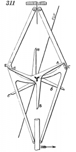
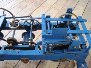
As previously mentioned the visit to Smith of Derby revealed that our clock would have had a double three-legged gravity escapement, not the pin wheel we were expecting. The clue was apparently the extra rail inside the back edge of the frame (cast iron, bolted on) to which the arbours attach, seen here at the bottom left of the picture.
On an equivalent Smith pin wheel clock this extra rail is not there and the arbours extend right to the back rail of the main frame.
The double three-legged gravity escapement is better at time keeping, especially on a turret clock. The impulse to the pendulum is not affected by any forces in the going train, so large hands covered in snow do not affect its accuracy. It was invented by Edmund Beckett for use in the clock commonly known as Big Ben.
While we hadn’t quite worked out how to make the pin wheel escapement, we think this one is going to be harder. As with a much of this project it’s the unknowns that make it difficult. We had studied all the pictures we could find of Smith pin wheel escapements and worked out a fairly plausible pin count and pendulum length. Now we have to do this again, but this time there are more variables.
Time for a couple more bits of useful info my Father got from his visit to Smith’s:
- The arbour we need to replace in the going train should rotate once per minute. You can put a small dial and a second hand on the end of it if you like. Since hearing this I have found an image of one that has a second hand.
- It was suggested that the clock probably had a 1.5 second pendulum and a 90:9 ratio coming off the escapement.
- All these old clocks were a bit custom made, they didn’t stick to plans (probably for good reasons at the time). This means there are no suitable plans that they could give us for a clock of this date. It also means that any info taken from another clock may not apply to this one.
Trying to put the first two facts together does not seem to fit and that’s where the third probably comes in. By my maths (which is not infallible) a 1.5 second swing advances the scape wheel a 6th of a rotation, which means 9 seconds per complete rotation. Turning a 9 pin lantern pinion against a 90 tooth wheel (a 1:10 ratio) means a 90 second revolution for the arbour, not the 60 you’d need to put a second hand on it. We need to move the next (existing) wheel in the train one tooth every 7.5 seconds, which would be possible if we had a 12 pin lantern pinion (instead of the 10 pin we have already made). So this is workable, but doesn’t give us a 60 second rotation of the arbour.
I’ve played with various permutations to try to incorporate as much info as we have, while still driving the rest of the train at the correct rate. The sensible options seem to be:
- 1.5 second swing, 90:9 ratio, 12 pin lantern – gives a 90 second rotation of arbour (as worked though above).
- 1.25 second swing, 90:9 ratio, 10 pin lantern – gives a 75 second rotation of arbour.
- 1.25 second swing, 72:9 ratio, 8 pin lantern – gives a 60 second rotation of arbour.
- 1.125 second swing, 90:9 ratio, 9 pin lantern – gives a 67.5 second rotation of arbour.
The engineer my Father spoke to at Smith’s sent him a picture of an escapement that probably comes from a similar clock. From what my Father told me it sounds as though they have a database of clocks they maintain, with pictures, and he looked up what he thought should be a pretty similar model. It’s difficult to count the teeth exactly in the picture, because you can only see a couple of sections of it, but it appears to have a 72 tooth wheel. Unfortunately you can’t see enough pins on the escapement lantern pinion to count them.

