A boot loader tutorial for ESP8266 using rBoot

From recent reading and discussions it seems that lots of people aren’t using the Espressif boot loader (or my own rBoot, but that’s less of a surprise) on the ESP8266. Why? Maybe people aren’t aware of the reasons why you might want to. Or maybe they can’t figure out how to – when I started playing with the boot loader it was poorly documented (probably still is) and I had to work it out myself.

I talk about “rom” or “roms” here to mean full compiled user apps, that might traditionally have been deployed on their own but with a boot loader you can have several on the flash with just one operating at a time. To avoid confusion (hopefully) I’ll refer to the rom section of code (the code that is run from rom, usually just the .irom0.text elf section) as irom from now on.

Why use a boot loader?

The main reason is to allow you to have multiple “roms” and to be able to switch between them. That may not sound quite as useful as being able to dual boot your computer between Windows and Linux, but there are uses for it. For example, if you want to update your device over the air (OTA) you’ll need to have at least two rom slots on your flash, a running one and one that’s getting flashed with the new version (which you then reboot into). There are work-arounds you could do to OTA update a device from the running rom, but it wouldn’t be very safe. OTA updates are probably the main reason for wanting to use a boot loader. However, you might have a need to deploy a device with two completely different functions and not want to combine them into a single application. With a boot loader you could put both separate apps on the device and switch between them remotely or with a GPIO etc.

Another reason is that the boot loader can load your application differently to the built in loader and add features not present in the original loader. For example the built in loader checks a checksum for the elf sections it loads into iram, but not for the .irom0.text section that is run from rom (this is often referred to as the SDK lib, but that’s also where your code goes if you mark it with ICACHE_FLASH_ATTR). A boot loader could add this extra check (rBoot can, it’s coded but not currently pushed to git), the Espressif loader doesn’t).

The Espressif 1.2 loader introduced a new format for the roms that puts the irom section (aka SDK lib) first and the iram sections immediately after. This means you don’t need to work with the arbitrary split of iram going before 0x40000 and irom after (you can change this split, but you may need to keep changing it as your sections change). Now the iram sections are still limited in size (because there is a finite amount of iram) but the irom section can be pretty much as large as the flash chip (minus the space needed for the iram sections, boot loader and SDK config (last 4 sectors of flash)), without needing to play with the linker scripts. With rBoot your options for laying out the flash are unlimited, so at present I’m not supplying sample linker files, but I do explain how to make them (it’s not hard).

How do you use the boot loader?

1) Think about how you want to lay out your flash, particularly how many roms you want and if they should be the same sizes. See below for a worked example.
2) Compile your code in the normal way.
3) Link your code slightly differently. For each rom slot on the flash you need a linker script – a copy of the standard eagle.app.v6.ld with one simple change. You need to link your object files against each one, to produce multiple elf files. See below for examples and an explanation.
4) Use esptool to build a rom image from each of the linked elf files, this time using the ‘boot_v1.2+’ option.
5) Write the boot loader to 0x00000 on the flash.
6) If you want something more than the simple 2 rom default create and write a boot loader config sector to the flash at 0x01000.
6) Write the roms to the flash at the appropriate addresses (see below).
7) Enjoy.

Linker Files

Why do you need new linker files and why do you need to link several times? I’ll assume if you are programming in C you understand the concepts of compiling and linking (but if you don’t it doesn’t really matter). The boot loader copies most sections to iram, this means they will always end up where you want them to be in memory, regardless of where they get placed on the flash. However the irom sections (usually just .irom0.text) aren’t copied, access to that code is via the memory mapped SPI flash. The whole chip is mapped at a base address of 0x40200000 so when you have multiple roms on your flash the irom section for each rom will be at a different place on the flash and so a different place in memory. When the code is linked the linker needs to know where that code will be in memory and the way to tell it is via the linker script. Short version: each copy of the rom on the flash needs to have been linked differently depending on where it will be flashed.

Example

I’ll make this one easy – a two rom setup, both the same size. A simple but common scenario (all you would need for an app with OTA updates) and rBoot will self configure for this when you run it.

We want two roms on the flash, so the sensible thing to do is place one at the beginning and the other half way along. We need to leave space for the boot loader and the config so we can’t put the first one at the very beginning, so we’ll start it at sector 3, flash address 0x02000. There is no reason that the second can’t start exactly half way into the rom, but for symmetry we’ll start that at half+0x02000 (and rBoot’s default config expects this). Lets say you have an ESP8266 board with an 4Mbit SPI flash, that second rom is going to be written to 0x42000, for 8MBit it will be 0x82000. If you have a flash larger than 8Mb the default position for the second rom will remain at 0x82000 due to the memory mapping limitation.

Now we need to make two appropriate linker files. Copy eagle.app.v6.ld to rom0.ld and rom1.ld. Edit rom0.ld and change the value of ‘irom0_0_seg org = ‘ from 0x40240000 to 0x40202010. This is the base memory mapped flash address (0x40200000) + our chosen flash address (0x02000) + the length of an extra header (0x10). Edit rom1.ld and set the value to 0x40282010. You can increase the len parameter in both of these too if you need more space for your irom section. Just don’t make it so big that it will overflow into the flash space of the next rom (or push the iram sections into it) i.e. the rom must come out at <512KB if you are going to fit two of them on a 1MB flash.

Now edit your Makefile and find the linker line, which is likely to start $(LD). You need to duplicate this and make one of them use rom0.ld, instead of eagle.app.v6.ld, and the other to use rom1.ld. Also make sure they output two different files, don’t have the second one write over the output of the first!

Now you should have two elf files, previously you would have just had one. What normally happens next appears to involve black magic, a Makefile, a shell script/batch file (gen_misc) and a python script (gen_appbin). This produces the flashable rom from the elf file. The whole thing is a mess and can be greatly simplified by using my esptool2 to build roms (other simplified tools also exist, I called mine esptool2 not to imply it is better or supersedes other tools, but just to distinguish it on my own system, way before I intended to release it). The key thing here is that you need to run it twice now, to produce two rom files from the two different elf files. You also need to instruct it to produce roms for what it describes as “boot_v1.2+” (the SDK boot loader v1.2+). However you are currently calling this will need to be updated, but I’d suggest switching to esptool2 if you’re using the original SDK code to do this.

Now just flash the three files (two roms and rBoot itself):
e.g. esptool.py –port COM7 -fs 8m 0x00000 rboot.bin 0x02000 rom0.bin 0x82000 rom1.bin

Using ‘-fs 8m’ here is important, it ensures the flash size is stored in the first few bytes of the flash, this will be read by rBoot to determine the flash size so it can work out where the half way point is.

On first boot you’ll see a message that a default config is being created and all being well the first rom will start. Assuming you got this far, hold on for part two where I’ll show you how to switch rom and/or OTA update from your app…
rBoot – A new boot loader for ESP8266

As promised here is my new boot loader for the ESP8266 – rBoot.

Advantages over SDK supplied bootloader:

  • Open source (written in C) – this is the big one.
  • Supports any number of roms.
  • Roms can be different sizes.
  • Rom slots can be used for resource storage as well as bootable apps (and benefit from the OTA update system).
  • Can use the full size of the SPI flash (see below).
  • Rom slots can be altered after deployment (with care!).
  • Earlier rom validation (less prone to errors).
  • Can try multiple backup roms (without needing to reboot).
  • Rom selection by GPIO (e.g. hold down a button when powering on to start a recovery rom).
  • Wastes no stack space  (SDK boot loader uses 144 bytes).
  • Documented config structure (easy to configure from user code).

Disadvantages over SDK supplied bootloader:

  • Not compatible with sdk libupgrade (but equivalent source included, based on open source copy shipped with earlier SDKs, so you can easily update your existing OTA app use this new code).
  • Requires you to think slightly more about your linker scripts, rather than just using the pair supplied with the SDK (but it’s not really that difficult – if you’re programming in C it’ll be well within your capabilities).

Problems common to both:

  • You still need to relink user code against multiple different linker scripts depending where you intend to place it on the flash, because the memory mapped position of the .irom0.text section needs to be known at link time. This also prevents you moving roms around at will once they have been compiled.
  • Only 8MBit of flash can be memory mapped at a time (the SDK bootloader allows at most the first 2 x 8Mbit chunks to be used for roms, rBoot doesn’t have this limit, on a 32MBit flash you can have 4 x 8MBit roms), see memory mapping imitation for more details.

Source code

I’ve decided to start putting my source code on GitHub, it’ll be easier to maintain keep my blog tidier.

https://github.com/raburton

Decompiling the ESP8266 boot loader v1.3(b3)

So having looked at the standard boot process on the ESP8266, let’s look at the boot loader and how it extends it.

The boot loader is written to the first sector of the SPI flash and is executed like any other program, the built in first stage boot loader does not know it is loading a second stage loader rather than any other program.

So what happens next? Well the second stage boot loader isn’t open source, it’s provided to us as a binary blob to use blindly. Of course we can work out roughly what must happen by examining the structure of the rom files used with the boot loader, but that’s not really good enough. Instead we must decompile the boot loader to see what’s really going on inside. This requires IDA and the Xtensa plugin and will give you an assembly listing for the boot loader. I can read this listing but it’s slow going and difficult to follow in this form. To really get an understanding I converted it to C code, which I have attached below. The nice thing about this is we can then potentially recompile it. Converting this to C and getting it to a point where it would recompile took me about 2.5 days! It’s a painfully slow process, but I’m sure someone regularly programming for embedded devices in assembler could have done it in a fraction of that time. The code below isn’t perfect, there are errors in my conversion process but it gives you a pretty good idea of what’s going on.

The basic boot loader process:

  • The boot loader is loaded like any other program.
  • It reads it’s config from the last sector of the flash (to know which of the two roms to boot).
  • It loads a second config structure from the second to last (for rom 2) or third to last (for rom 1) sector of the flash.
  • It finds the flash address of the rom to boot. Rom 1 is always at 0x1000 (next sector after boot loader). Rom 2 is half the chip size + 0x1000 (unless the chip is above a 1mb when it’s position it kept down to  to  0x81000).
  • It copies some compiled code, from the .rodata section of the boot loader, to the top of iram and executes that code, passing it the flash address. I’ll call this the stage 2a loader.
  • That stage 2a loader actually performs the same basic functions as the first stage loader – it copies the iram elf segments and calls the entry point.

The new rom header format

The roms loaded by the boot loader can be of the standard 0xe9 format or of a new type. The new type is basically a normal 0xe9 rom proceeded by a new header and the .irom.text section. The new header is as follows:

typedef struct {
	uint8 magic1;
	uint8 magic2;
	uint8 config[2];
	uint32 entry;
	uint8 unused[4];
	uint32 length;
} rom_header;

magic1 is 0xea. magic2 is 0x04. entry is the entry point point of user code. length is the length of the .irom.text segment. This header is then followed by the .irom.text segment, then a standard 0xe9 header and elf segments. The boot loader skips all the new stuff and loads from the standard 0xe9 part as normal.

So why so complicated?

  • Some of it may be the compilation and decompilation process – that can change the structure quite a bit from the original. I don’t know if it was originally written in C or ASM.
  • Why memcpy code into iram rather than just running it in the normal way? The boot loader is already running from iram where the user code needs to be copied to. That would break it, so the extra loader stage is deployed to the top of iram, which is assumed to be spare and safe (as long as the user code doesn’t try to load a section there).
  • So why not just load the boot loader to the top of iram in the first place? The first stage loader will not load sections to an address that high in iram, I don’t know why but I tested it and it simply doesn’t work.
  • Why not not run the loader entirely from rom? The flash isn’t memory mapped at this stage, so that’s not an option, pity.
  • Why the new rom header? By putting the .irom.text section first it can have a known address on the flash (so will be mapped to a known address in memory) and all the space after it is available to store your iram sections. The original format had the .irom.text after the iram sections, so you needed to adjust the linker script and position on the flash if you wanted to rebalance your sections.
  • Why does it need 3 x 4kb sectors of the flash to store only a handful of bytes of config? I can’t see a good reason for that.
  • Why do they have so many copy routines depending on the size of data to be copied? I can only assume someone thought it was more efficient, maybe it it is but I’m sure the performance benefit would be negligible and it certainly makes the code a lot more complicated than it needs to be.

There are various other details, like extended mode and switching to backup rom, have a look at the code if you want to know more.

Problems with the loader

  • Not open source – can’t modify it.
  • Only two rom slots.
  • Uses 144 bytes of stack space, which cannot then be used by user code.
  • Image is validated by the stage 2a loader, if there is a problem with the image (e.g. bad checksum) the code returns to the 2nd stage which might have been overwritten already.
  • No checksum on .irom.text section.
  • Overly complicated code, possibly buggy (I’ve often OTA updated my device and found it won’t boot afterwards without clearing the loader config sector, but this could equally be bugs in the OTA update code).
  • Trying the backup rom requires a reboot, not a big deal but also not necessary.

C source for boot loader 1.3(b3)

Should just about compile, but don’t expect it to work propery as-is. Just for your education. Stage 2a needs to be compiled and the compiled code needs to be extracted and put as data into stage2 code, see the memcpy at line 254 for where it’s used.


ESP8266 boot process

I decided to write my own version of esptool for windows to create rom images. Although there is already a windows version available it can’t create new type firmware images for use with the latest versions of the boot loader from the espressif sdk (e.g v1.2). I could have just used the python version, but as with all this playing it was as much for my education and entertainment as for any practical purpose. In the process I ended up learning more about the boot process than I expected and writing my own boot loader.

As I haven’t seen a lot of info about it online I thought it might be useful to document the normal boot process here. The built in first stage bootloader reads the start of the SPI flash where it expects to find a simple 8 byte structure:

typedef struct {
	uint8 magic;
	uint8 sect_count;
	uint8 flags1;
	uint8 flags2;
	uint32 entry_addr;
} rom_header;

The magic value should be 0xe9. sect_count contains the number (may be zero) of elf sections to load to iram (this does not include the .irom.text section). flags1 & flags2 control the flash size, clock rate and IO mode. entry_addr contains the entry point to start executing user code from.

After the header come the actual elf sections. Each is headed by another 8 byte structure (followed immediately by the data itself):

typedef struct {
	uint32 address;
	uint32 length;
} sect_header;

The first stage boot loader verifies the magic and sets the flash mode according to the flags. Then it copies each section to the corresponding address from the header (which should be within the iram section starting at 0x40100000). As the sections are loaded a single checksum is created of all the data (headers are not included). If the final checksum matches the one stored at the end of the elf section on the flash it will call the function found at entry_addr.

The whole of the flash is also mapped to an area of memory from 0x40200000. The .irom.text elf section just sits somewhere on the flash after the other elf sections and does not have a header like those destined for iram. The default linker script eagle.v6.ld bases the section at 0x40240000 so it should be written to 0x40000. This mapping does not occur until later (presumably by sdk library code), so you can’t access the flash directly in memory in the boot loader – it must be accessed through spi read calls.

A simple NTP client for ESP8266

Once you have a real time clock working on the ESP8266, you might actually want to set it. As they have a backup battery you may just set it before you connect it to the ESP8266 and forget about it, but that’s not ideal. These cheap RTCs probably aren’t perfectly accurate and if it stops for any reason (e.g. dead backup battery) you’ll need to reset it. The DS3231 has a flag to indicate it’s been stopped – ideally this should be checked on startup and the clock set via NTP if there has been any interruption.

I did find one other simple NTP implementation but it’s incomplete, there is no timeout and it doesn’t clean up the connection when it’s finished (so it’ll leak memory). I think my version should work a little better, but I can’t guarantee it’s bug free so please let me know if you find any. As well as getting the time, the code is a nice simple example of a UDP client.

To use simply call ntp_get_time( ). The NTP request is asynchronous so you get the time in the ntp_udp_recv callback function, have a look there for two simple examples of what you could do with your newly received NTP time (print it out or set an RTC).

Code now on GitHub: https://github.com/raburton/esp8266

AT24c32 for the ESP8266 (C code)

The AT24C32 (24c32) is a small eeprom that comes on popular, dirt cheap, RTC boards (but of course is also available separately). Using the datasheet it’s easy enough to get working on the ESP8266. All the AT24C series chips work the same, except for an extra address bit in the 1Mb version, so the example code below can be used with any model (see the note in the header file about the 1Mb chip).

The chip basically has two operations:

  • Read from current position.
  • Write to specified position.

Technically there is no read from specified position. To do this you must make a dummy write, as the datasheet refers to it. This basically means starting a write operation, which begins by setting the address, then not sending any actual data (or an I2C stop). Instead you perform an I2C start again and perform a read as normal.

When reading you can read as much data as you like. When writing you can only write up to 32 bytes at a time. A write operation is restricted to a single 32 byte page (or part of one). You do not need to start at the beginning of the page. Regardless of where you start in a page, if you continue to write after reaching the end of the page you will wrap back to the start of it and continue writing there. This means you need to keep track of how much you are writing and where the next page boundary is.

The example driver code attached, written for the C API of the official Espressif SDK, handles all the issues above. You can write as much as you like, wherever you like – it will perform multiple write operations across pages as you’d expect. You can can also read from specified locations and the driver will perform the dummy write for you to set the starting address. You can still read from the current position and write inside a looping page if you like. You should be able to drop this code straight into your ESP8266 project, set the I2C address in the header file (according to your address pins) and start reading and writing to your eeprom with ease.

Code now on GitHub: https://github.com/raburton/esp8266

Feeding the watchdog on ESP8266

I wanted to do some waiting in a tight loop on the ESP8266, but that can lead to a watchdog timeout and a reset. I figured there must be a way to stop that but there isn’t anything in the documentation. Grepping the libs I found a couple of candidates and, after trying them all out, I found exactly what I was looking for – slop_wdt_feed. Declare the following in your header:

extern void slop_wdt_feed();

Now just call it in any long running loops or functions and it’ll keep the  dog off your back. Note this isn’t necessarily good practice!

At time of writing google returns exactly one result for this function name (just a listing of functions in the library) so I don’t think this is currently widely know.

Update: As of SDK v1.1.1 (possibly a little earlier) this no longer works. You can now use these (from Pete Scargill’s blog):

extern void pp_soft_wdt_stop();
extern void pp_soft_wdt_restart();

Mutex for ESP8266

I don’t know what can interrupt user code on the ESP8266 or what might do the interrupting, the documentation is lacking in that area, but something seems to be causing me a timing condition. With a really low time out on an NTP call I seemed to end up in the receive and the timeout code at the same time. The timeout kills the connection and the receive disarms the timeout, so in theory only one should ever be run, but what happens if the timeout occurs between the receive code being called and it actually disarming the timeout? Will the timeout interrupt the receive, kill the connection and then allow the receive code to continue? That is what it looked like, so I did the obvious thing and searched the API for some kind of mutex. No joy, but the whole API isn’t documented so I grepped the SDK libraries for any function name that might be relevant, still no joy. I’ve come to the conclusion the SDK does not provide any such functionality, so I had to get my hands dirty with some assembler…

Armed with a copy of the Tensilica Xtensa Instruction Set Architecture reference manual I tested out the S32C1I operation. The GCC compiler doesn’t know this instruction or the special register it uses (SCOMPARE1), so I wrote something similar and patched the right opcodes into the assembled object file. Unfortunately trying to write to this register reset the device, so it looks like the ESP8266 does not support the ‘Conditional Store Option’, darn.

So, I’m not sure how I ended up at it but I found some Linux kernel code with what appears to offer the solution and forms the basis of my esp8266 mutex code. The code is easy enough to use – declare a mutex_t, call CreateMutux against it, then GetMutex and ReleaseMutex as required.

Code now on GitHub: https://github.com/raburton/esp8266

Simple timezone support for the ESP8266

I suggest you run your RTC on GMT (aka UTC, if you’re French). If you’re just using it for data logging or the like you can probably run entirely in GMT. If you want to display it to a user you probably want to do that in localtime. The ESP8266 C API doesn’t have support for timezones, so you’ll need to add your own. Adding or subtracting a few hours is easy enough, but applying daylight savings time (DST) during the summer is a little more tricky. A quick google search found a few examples but they all assumed the adjustment happened at midnight, so I’ve created an extended version that changes at 2am, as happen here in the UK. This is an example and will need to be modified if you’re not in the UK. Ideally the function would parse a string with timezone specific definitions rather than having hard coded rules, if you want to do this hopefully this code will serve as a starting point.

Code now on GitHub: https://github.com/raburton/esp8266

Real time clock (DS1307/DS3231) for the ESP8266

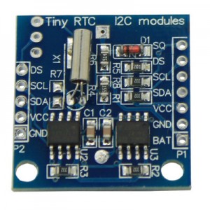
Cheap DS1307 "TinyRTC" board

Continuing the time theme, I’ve recently been playing with the ESP8266 wifi soc and the common real time clocks (RTCs) DS1307 and DS3231. It seems to be popular to program these devices with LUA using NodeMCU firmware, but I can’t work out why. LUA seems to be pretty awful, but I guess if you’re new to programming it’s an easy way to get started and you aren’t likely to notice how odd LUA is. Real men use C (or assembler, if they’re showing off).

(TL;DR – skip to the bottom of the post for the attached C code.)

So you can program for them in C, using the SDK supplied by the manufacturer (which is what NodeMCU itself is built with). Actually they supply two SDKs: The first is the one they are actively pushing for development and offer bug bounties for. The second one (FreeRTOS based) seems to use more standard APIs and appears to have a few more features, but it’s future isn’t clear. It’s a bit confusing, but I’ve decided to stick to the first SDK.

So, back to the RTCs… These are easily obtained from China for about 53p from AliExpress, shipped to the UK! Amazing when you consider you can’t even send a letter inside the UK for that price. You basically have a choice of two boards, one based on the DS1307 (pictured above) and one with the DS3231 (below). The DS1307 has less features than the DS3231 and the boards, generally labelled as TinyRTC, seems to be pretty flaky – my advice would be to avoid them. Lots of people find they don’t work without modification. Mine works (after mods), but only with power applied, it doesn’t maintain it’s timekeeping on battery.

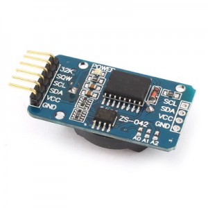
Cheap DS3231 board

The DS3231 is more accurate, has more features and the boards seems to work fine. As they’re the same price I’d go for these every time. Note that both boards are designed to be used with a rechargeable lithium cell battery, and if you put in a normal CR3032 it will try to charge them and they might explode! On the DS3231 board you can simply remove the diode to disable the trickle charge circuit. Also of note, both boards come with an AT24C32 i2c eeprom on board, which might be handy for something.

So why do you need a RTC? The device has wifi so why not just get the time from an NTP server? Well you might not want wifi enabled all the time, especially if you intend to run the ESP8266 from battery. Getting the time from the RTC is quicker than NTP,  and easier to do synchronously. You can also do other neat things, like use the alarm on the DS3231 (not available on the DS1307) to wake the ESP8266 from sleep, it could then connect to the network check in with a server to send data/ receive instructions, then go back to sleep again. The DS3231 can even tell you the temperature.

I found a few simple examples of using these RTCs for LUA, but nothing much for the C API, so I’ve written drivers for both. I think they are pretty comprehensive in their support for the features of the chips and the code is thoroughly commented so you should be able to work out how to use/ modify it easily.

Code now on GitHub: https://github.com/raburton/esp8266