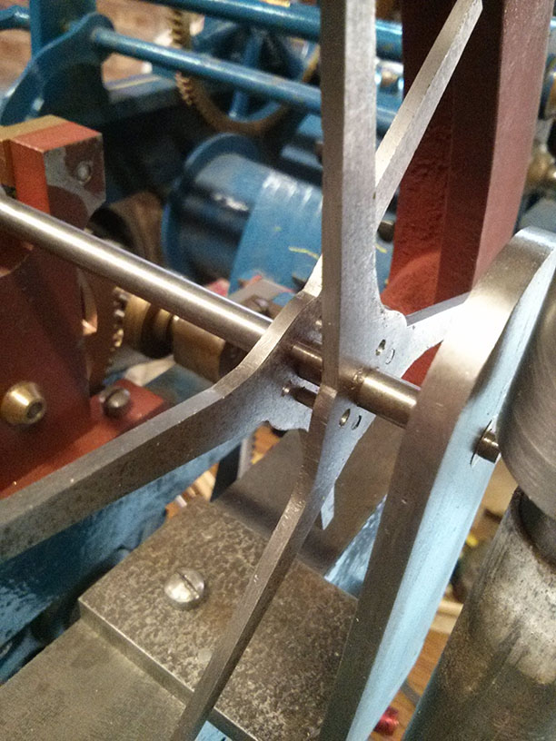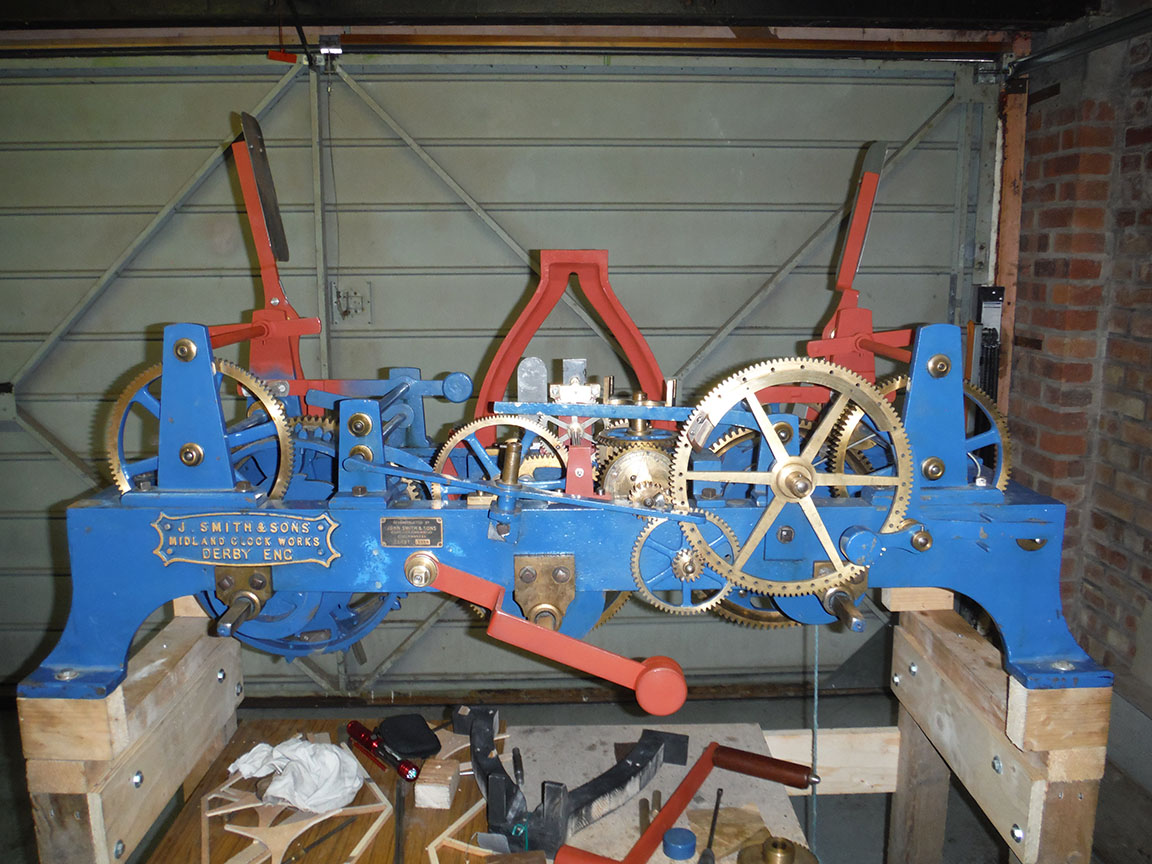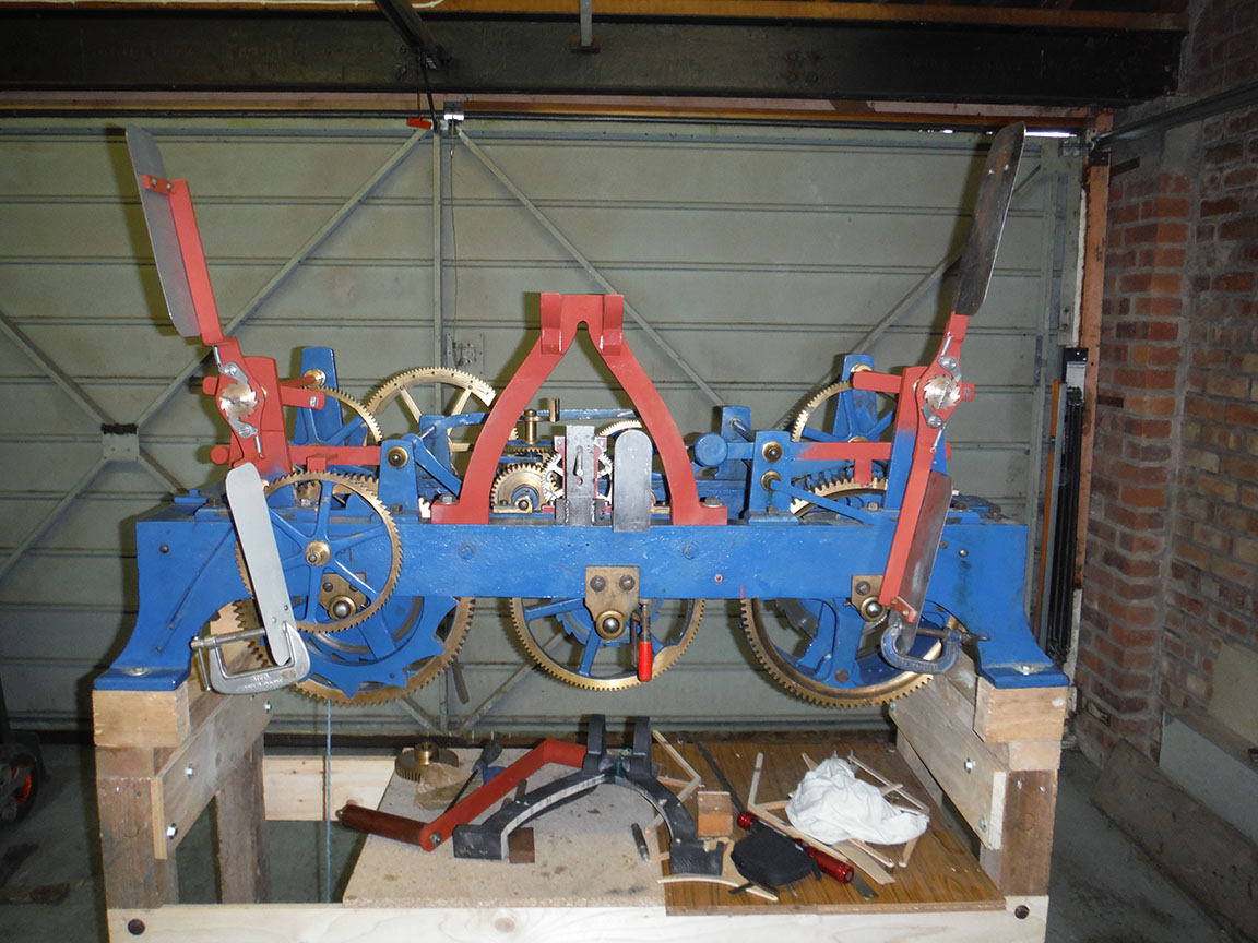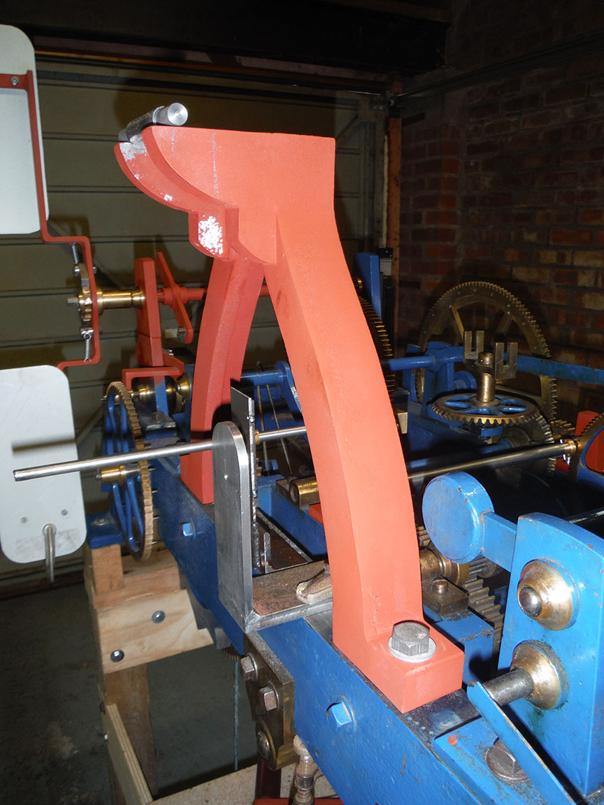
It’s been a while since my last post about the turret clock restoration project, not least because there wasn’t a lot of progress over the winter. For a long time we were struggling to work out how the double three-legged gravity escapement itself was constructed. Unfortunately, several offers of help with this didn’t come through but we have managed to work something out that that fits the brief. As always there are a number of ways something like this could be done, but we wanted to replicate the original. Visually we have done that so we must be pretty close, but we don’t know how close.
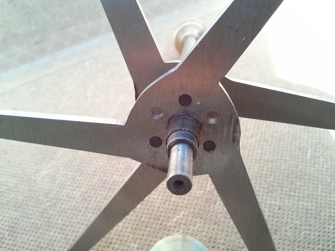
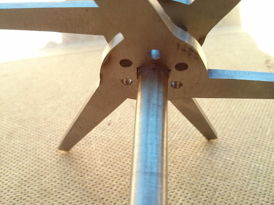
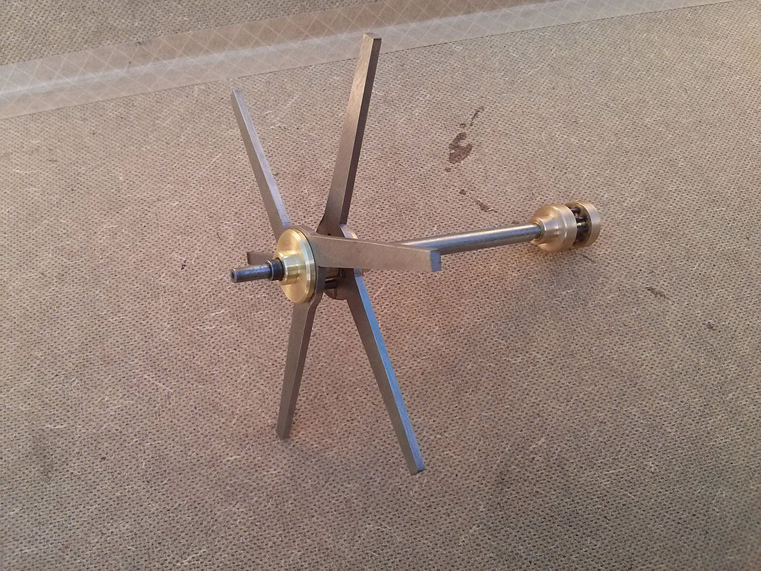
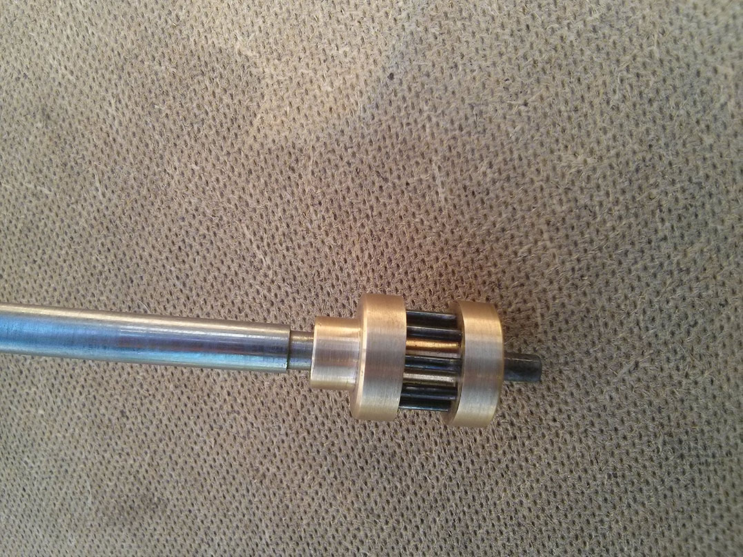
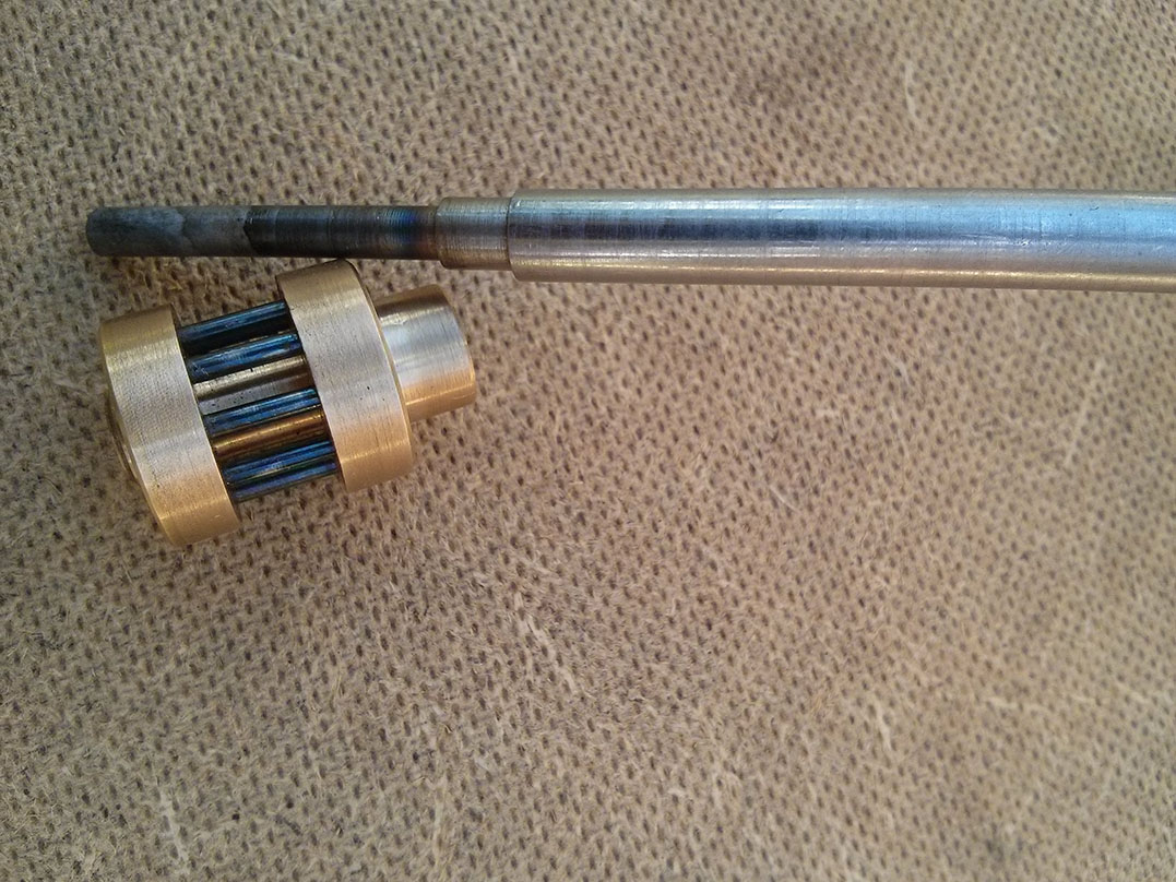
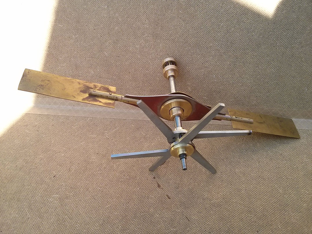
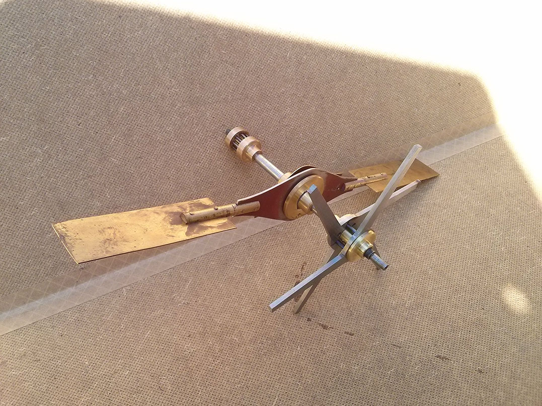
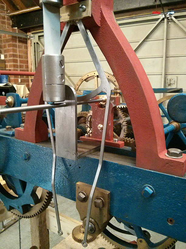
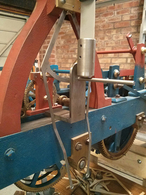
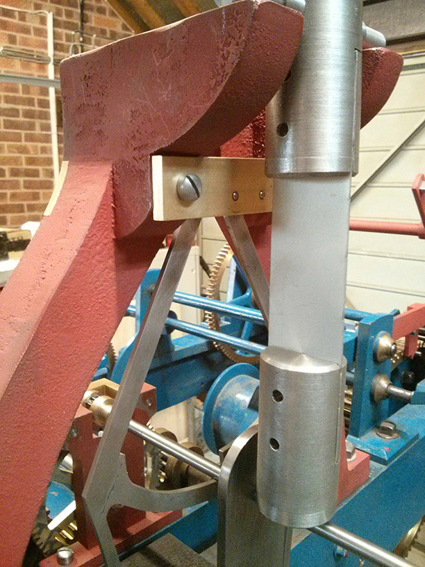
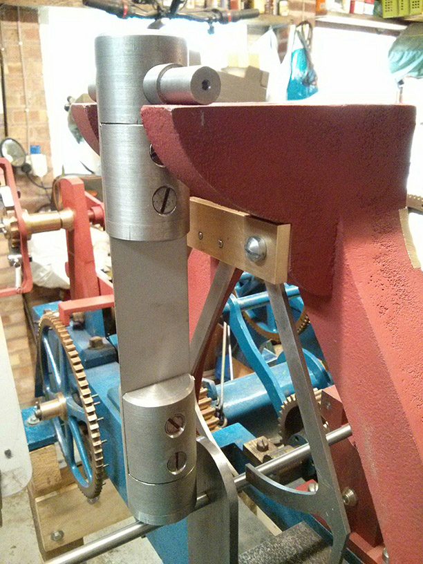
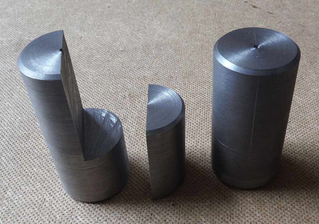
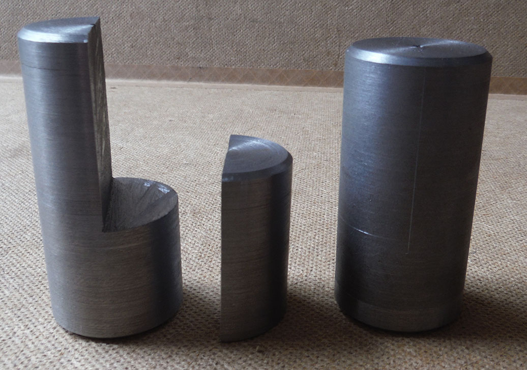
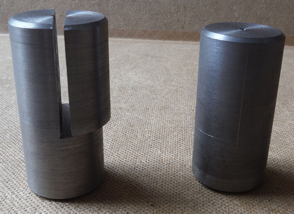
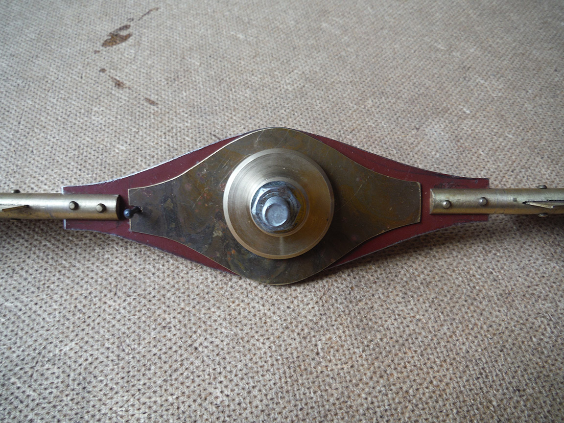
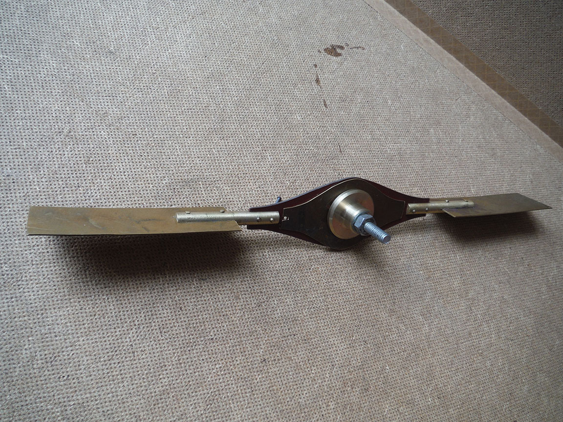
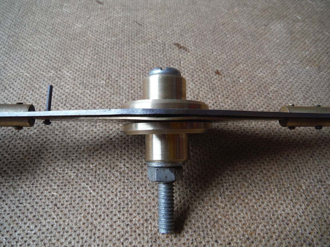
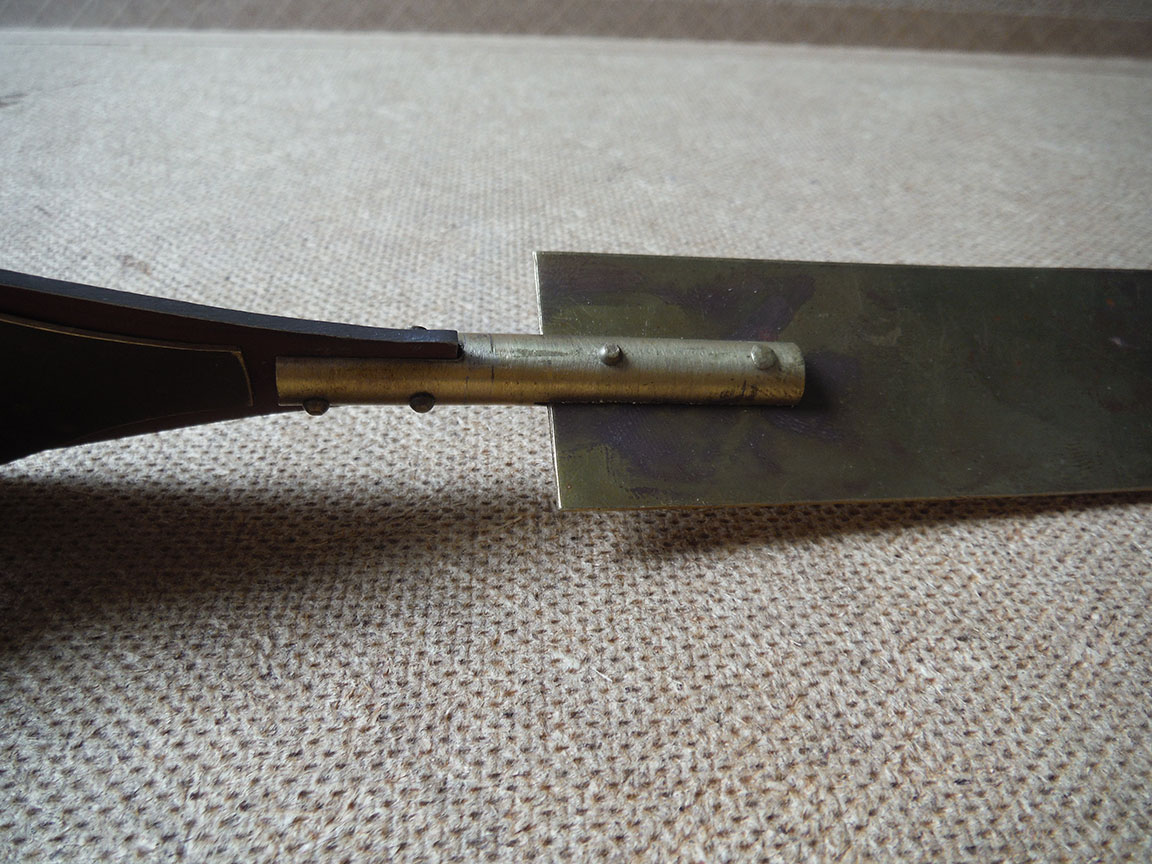
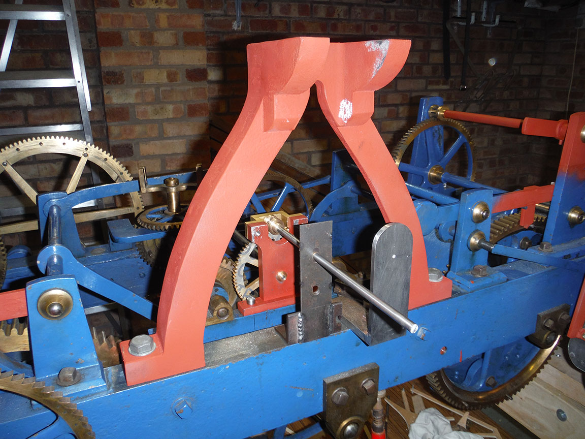
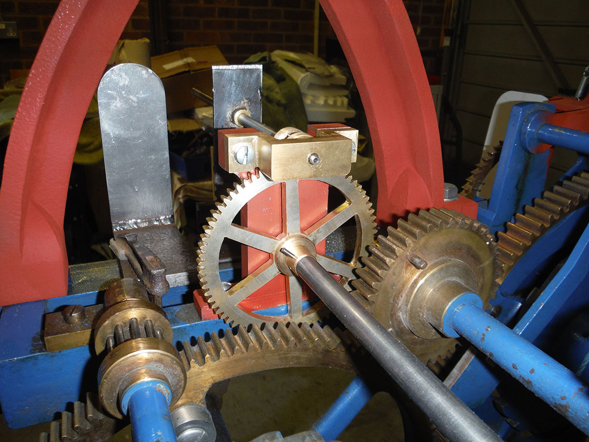
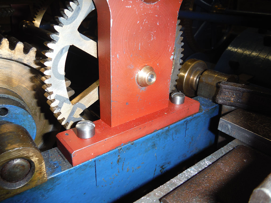
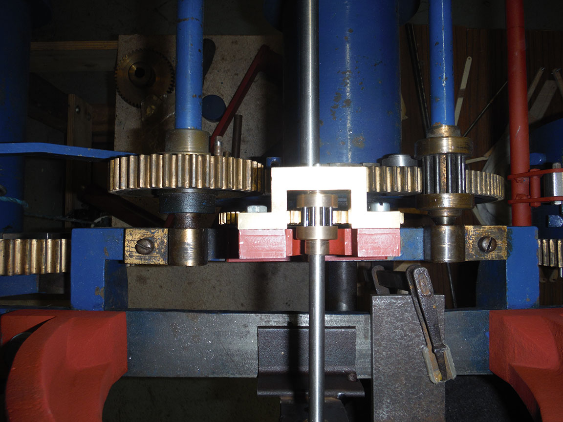
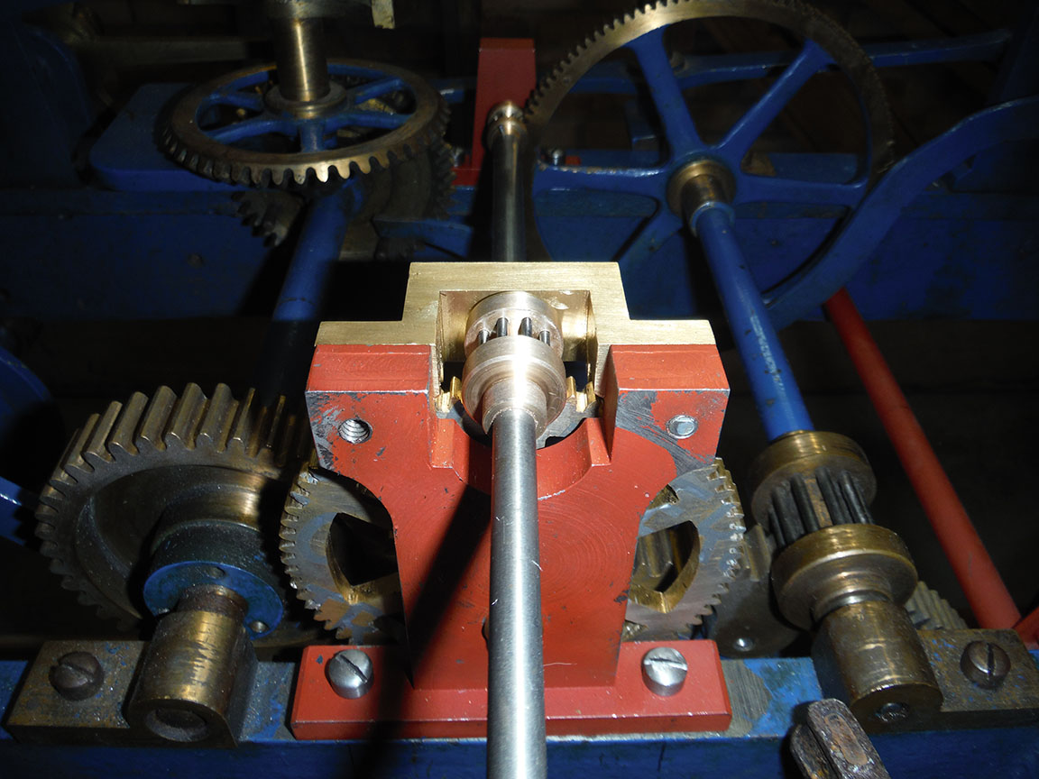
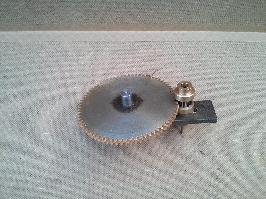
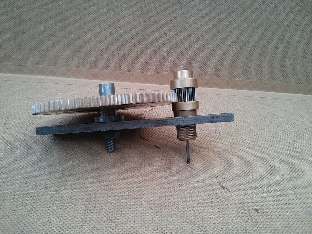
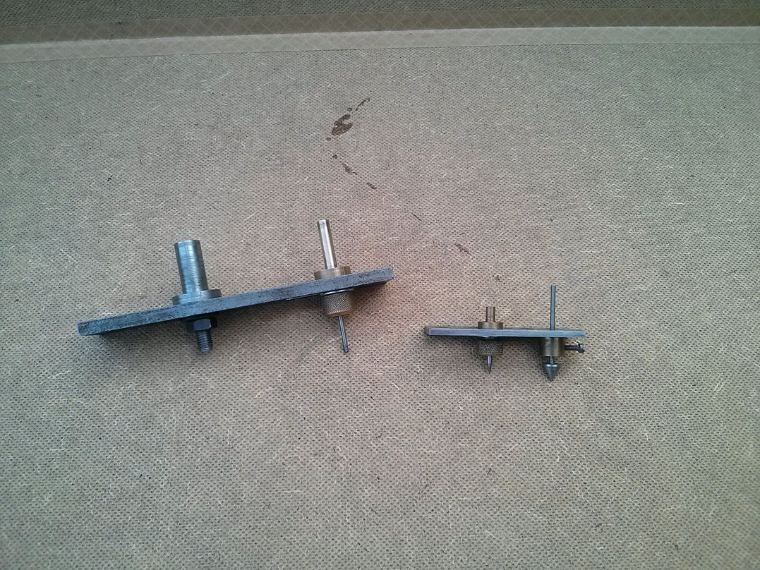
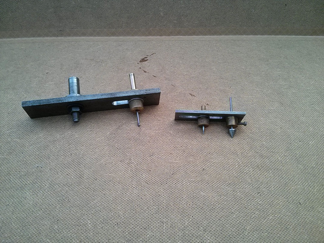
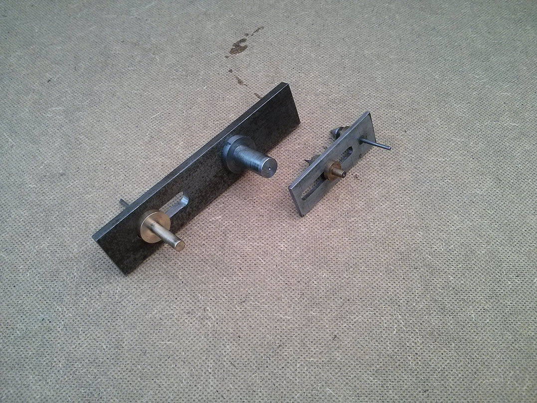
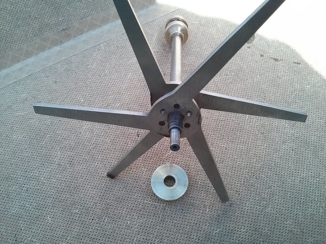
The method we used was to turn down a hexagonal bar to make the arbour, leaving a short hexagonal section on which to mount the two escape wheels. The hexagonal mount gives the wheels good solid attachment to the arbour preventing any rotation as they hit on to the blocks and stop moving. We can see no way that they could have been pinned to a round arbour and we didn’t think silver soldering them would be sufficient due to the repeated blows they must endure. A small section of brass tube fits over the hexagonal section between the two wheels to keep them the correct distance apart. The three lifting pins are installed between the two wheels in simple holes straight through. A boss fits on either side to sandwich the wheels and tube together and keep then in place, as well as covering the pin holes to keep the pins in. The bosses could be pinned to the arbour, but they don’t appear to be on the original. The arbour isn’t a large diameter and the bosses don’t have a lot of depth to take a pin. As they only need to hold the parts of the escape wheel together, they don’t take any force, we decided to silver solder them on to the arbour. Overall we think our construction technique must be pretty close to that used on the original, but it’s hard to inspect this part on a working clock – our reference clock is viewed from eight feet up a ladder, with the escapement at the back and everything is moving.