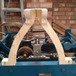
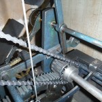
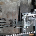
Pendulum support casting

Pendulum casting pattern, front view

This is the first update for a while on the clock, but we are still working in it. It was a bit cold for spending long in the workshop over winter. Then, as things picked up in spring, there were plenty of other priorities. As well as creating the pattern for the pendulum support casting we now have all the key measurements and positions worked out for the escapement. We have also started work on another missing wheel (but more on that in another post to come).

When the clock was converted to electric drive it was became little more than a gear train from the motor to the drive shaft. It no longer used a pendulum or escapement and unfortunately these were not kept with the clock. The pendulum would have been mounted on a large cast iron wishbone-shaped casting at the back of the clock. The arms of the escapement were also attached to this structure.

The pattern for the casting was made out of a couple of chunks of pine joined together. The basic shape was cut out with a band-saw. A small amount of hand carving was required for fine details and wax fillets were applied to the recessed front edge. Dimensions for the arch were taken from the clock of St. Alkmund’s Church, Duffield. The measurements were taken in situ, from the top of a ladder, while the clock was going. As a result they may not be quite 100% accurate, but very close to the original.

My father approached a couple of local foundries about casting the pattern. I was surprised there were any local foundries left, let alone a choice, but then Derbyshire was the birthplace of the industrial revolution! Neither of us really knew how much it was likely to cost but we were disappointed with the first quote of over £160. In the end we managed to get it for £55, with a 3 week turnaround. We’re still waiting and I’ll post pictures once we get the finished article. It’s going to need a little machining to complete. The base needs to be made flat and a v-shaped groove cut across the top for the pendulum to sit in. It also needs to accommodate two brass plates, one on the front and one on the back, to mount the arms of the escapement.

Flash write bug fix

Looks like I finally have a fix for the flash write issue, thanks to some help from Espressif. Embarrassingly it turns out to be my fault, but I’m not too proud to admit that. So what was the problem? Since SDK v1.5.1 people have been reporting intermittent failed OTA updates and I’ve been able to reproduce it easily myself. This only seemed to occur when using wifi for long sustained writes.

So what was happening? Occasionally the network receive would get a much larger packet than normal. In my latest testing they are usually around 1436 bytes, but occasionally one would arrive that was 5744 (this is the only large value I have seen myself, but presumably other values could occur). The flash is erased in 4k sectors and the rBoot code erases them as required, checking if the current data block will fit in the current sector and if not erasing the next one too. Where I went wrong was to assume that a receive would always be less than the 4k sector size, having never seen one before SDK v1.5.1 that was anywhere near that large. When one of these very large packets arrives it could span 3 sectors. The second sector would get erased correctly but the third sector would not. The flash write command would not return an error when it tried to write to the non-erased sector, so no fault was noticed at this time. Then on the next write that third sector, now being the first sector for that next write, gets erased and the new data written part way through it (where it should be).

Moral of the story. Don’t make assumptions and don’t ignore the edges cases – I’m usually pretty good at this second point, but occasionally I seem to need reminding. In this case I had thought about it and added code that detected a chunk over 4k that would need more erasing. As I didn’t think this could ever happen I merely put a comment in the if statement to say what would need to be done in that scenario, if I’d thrown an error at that point instead this problem would have been easily diagnosed. However, I did also assume that the flash write would fail if it tried to write to flash that was not erased, so I expected to see an error of some kind.

Why did it suddenly happen at v1.5.1? I don’t know that but presumably Espressif made some change in the SDK that makes this more likely to occur. While playing with some code for Pete Scargill I did manage to reproduce the problem with v1.4.0 so it wasn’t impossible for it to happen there, but I never had any reports of it there previously. I also found that the timers in Pete’s code made it more likely to happen in my testing, so I suspect the extra processing these caused was impacting the performance of the network stack and causing more packets to be bunched together and delivered as larger chunks to the application. Further testing showed RF interference could also cause the same result.

The fix is available in the rBoot GitHub repo, and has also been updated in Sming.

Flash write bug in Espressif SDK v1.5.1+

Users of rBoot have reported OTA problems when using Espressif SDK v1.5.1 which I have been able to reproduce on this version and v1.5.2. The problem appears to be in the sdk flash write functions. While most writes work fine some will occasional fails to fully write (leaving small areas of blank data (0xff)). To make matters worse no error is reported from the write function and attempts to read the flash back for verification immediately afterwards return the correct data (presumably they are serviced by the rom cache). This is very similar to the problem seen when trying to perform an OTA with insufficient power. I once had a similar report from a user using just a 100mA power supply and the problem was fixed by using a proper power supply. This makes me wonder if the new SDK causes the device to draw more power, although supplying extra power does not fix the problem in this case.

I have created a test case that doesn’t use rBoot but simply downloads a file and writes it to flash (which is of course very similar to what rBoot does) to demonstrate the problem to Espressif. I have yet to hear back from them. If you encounter this problem please add your support to my bug report. I have no reason to believe this bug will be limited to rBoot users and I assume SDK bootloader users and anyone else writing to the flash from an application (possibly only in long sustained writes) will also have this problem.

This is a good opportunity to encourage rBoot users to enable the irom checksum option, to help detect badly flashed roms at boot time. See the readme for more information.

New rBoot version allows temporary boot

I’ve just pushed an update to rBoot that allows 2-way communication between rBoot and the running user application. This is something I had though about previously, and I mentioned it in a previous post, but nobody had actually asked for it until a couple of weeks ago. The main use of this is to allow the application to request rBoot to perform a temporary boot to a different rom (i.e. not the one identified in the config, which would normally be booted). This helps to make updating safer, because you can perform an OTA and only temporarily switch to the new rom, until you are happy to update the config and make this the standard. rBoot is already safer for updating than the SDK bootloader, if you enable to irom checksum option, but this new functionality also guards against valid but buggy roms that simply don’t work properly once booted.

How you decide that your rom is good enough to switch to booting it by default is up to you of course. Perhaps if the rom is able to boot, connect to wifi and stays up for 5 minutes, that would be deemed sufficient. Another option would be to have the user manually initiate the change of default rom once they are happy with the way it runs.

You can also get information about the boot from your application such as the boot mode (standard, temporary or GPIO), and the currently running rom. Previously the running rom could be determined by reading the config, but that would not work for a temporary boot.

This new functionality makes use of the ESP8266’s RTC data area and to use it uncomment the #define BOOT_RTC_ENABLED line in rboot.h. See the documentation in the GitHub rBoot repository and the updated sample project for example use.

One other change made at the same time is that GPIO-rom selection is now an optional feature and not compiled in by default. Please enable the appropriate #define in rboot.h if you wish to use this feature.

Going train revisited

Diagram of the going train

After examining the St. Alkmund’s clock we are able to start making some progress again. However, as the going train isn’t exactly the same as ours, we still don’t have all the information we need. Some details still need to be worked out. It’s also worth noting that even if it had had the same as the parts that we currently have, there is no guarantee that our missing parts would have matched – the engineer at Smith of Derby said there was a lot of variation between clocks. We may never know exactly what the original train was on this clock, so we will have to go with something sensible.

Yesterday, my father discovered something interesting we had never noticed before. The missing front arbour support, for the missing arbour, was attached to the frame by two bolts. The same support on the clock at St. Alkmund’s is attached by one bolt. That may not sound very important, and it’s possible we are reading too much into it, but of all the pictures of Smith flat bed turret clocks of this vintage we can find there is only one other that has two bolts for this support. The other is the clock at Trinity Collage, Cambridge. That clock has an extra dial at the end of this arbour and a second hand – something else the Smith engineer mentioned our clock could/ should have had. It is the presence and position of the extra dial that requires the two side bolts for fixing the support, rather than a single bolt through a front “foot”. (I’ve previously mentioned how similar I though our clock was to the Trinity clock (except for their unique fourth train) and I did contact the keeper for more details about the clock, but unfortunately never received a reply.)

So, if we assume from this observation that our clock had a second hand then that fixes the rotation speed of the missing arbour to one rpm. As the lantern pinion at the front end of this arbour must turn the 120 tooth wheel at a rate of one tooth every seven and a half seconds then that pinion must have eight trundles. Suddenly we have two less unknowns in the train!

I previously suggested some options for the missing parts of the train, but if we take the above (60 second rotation, 8 pin pinion) as correct we can improve the list of options:

  • 1.5 second swing, 60:9 ratio at escapement.
  • 1.25 second swing, 72:9 ratio at escapement.
  • 1.125 second swing, 80:9 ratio at escapement.
  • 1 second swing, 90:9 ratio at escapement.

The engineer at Smith’s did suggest a 90:9 ratio, but I find it hard to imagine this clock only had a one second pendulum. That’s only about a metre, the same as a typical long case (“grandfather”) clock. The pendulum at St. Alkmund’s is 1.5 seconds or about 2.24m. The Trinity clock pendulum is described as being “2 metres” but it’s not clear how they are measuring it. The length of a pendulum is measured from the pivot to the centre of mass and so the overall physical length of the pendulum may be quite a bit longer. 2m is not a standard/ common length so I suspect it’s an approximation of the physical length rather than an accurate “functional length”.

As we’ll never know what this clock originally had we can choose one of the above options, keeping in mind the practicalities of the pendulum length. Only the 1 second pendulum would fit the clock on its current stand and would be the most convenient length, but that feels too short to me. The 1.5 second pendulum is far too long to be practical, so our current intention is to make it with a 1.25 second pendulum and 72:9 ratio. We just need to make sure that actually fits around the rest of the escapement mechanism.

Clock of St Alkmund’s Church, Duffield

St. Alkumund's Church, Duffield, Smith of Derby turret clock

Unfortunately here has been little progress on our clock over the summer as we have been stuck on the escapement. However, we have finally managed to track down a suitable clock for us to model our missing escapement on. The clock is of course a J Smith & Sons, Derby and is of pretty much the same size and design as our own. In the end we didn’t have to go far to find it either, about 5 miles from my house is St Alkmund’s Church, Duffield. Where, coincidentally (or probably not), I will be getting married next year. I must thank Mike Banks (previous clock keeper), Luke Heaton (tower captain) & James Buchanan (assistant minister) for making this visit possible.

The clock is slightly older than ours at 1897 (vs. 1922), and there are a number of differences, but many of the important details are the same.

Some differences:

  • The going train is geared differently, unfortunately I can’t say exactly what it is because it’s very difficult to count teeth on a working clock, up a ladder, without touching it or putting chalk marks on it.
  • The going train winding arbour passes through the frame rather than being mounted under it (the other two trains are mounted under, as are all three on our clock). This seems to be the norm on these slightly older models.
  • The larger lantern pinions on our clock are more like regular pinions (but with closed ends) on this clock.
  • It has a five bell chime, ours has eight (although, unlike us, St Alkmund’s actually have the bells to go with it, in fact they have an impressive ten bells in total).

Now we have measurements for lots of details we didn’t before, as well as having actually seen one up close (which makes a big difference). We are now in the process of drawing up the missing parts and planning the next steps of our restoration.

Here are some pictures of various parts of the clock we wanted a closer look at.

rBoot now in Sming

rBoot has now been integrated into Sming. This includes rBoot itself (allowing the bootloader to be built alongside a user app) and a new Sming specific rBoot OTA class. The sample app from my GitHub repo has been improved and included under the name Basic_rBoot, it demonstrates OTA updates, big flash support and multiple spiffs images.

The old sample app will be removed from my repo shortly. If you want to make use of rBoot in Sming it’s now easier than ever – just use release v1.3.0 onwards, or clone the Sming master branch, and take a look at the sample project.

C Version of system_rtc_mem_read

Here are C versions of system_rtc_mem_write & system_rtc_mem_write. You don’t need these when your app is compiled against the SDK but if you are running bare-metal code you might find them handy. You could add this code to rBoot so you can communicate with it between boots, e.g. setting a flag from your app to alter the behaviour of rBoot on next boot.

Note: in the SDK version if you specify a length that is not a multiple of 4 the actual length read will be rounded up and so it may overflow the supplied buffer (although alignment/packing of memory may mean this isn’t a problem), my version requires a read in multiples of 4 bytes, but you can easily remove that check if you wish.

uint32 system_rtc_mem_read(int32 addr, void *buff, int32 length) {

	int32 blocks;
	
	// validate reading a user block
	//if (addr < 64) return 0;
	if (buff == 0) return 0;
	// validate 4 byte aligned
	if (((uint32)buff & 0x3) != 0) return 0;
	// validate length is multiple of 4
	if ((length & 0x3) != 0) return 0;
	
	// check valid length from specified starting point
	if (length > (0x300 - (addr * 4))) return 0;

	// copy the data
	for (blocks = (length >> 2) - 1; blocks >= 0; blocks--) {
		volatile uint32 *ram = ((uint32*)buff) + blocks;
		volatile uint32 *rtc = ((uint32*)0x60001100) + addr + blocks;
		*ram = *rtc;
	}

	return 1;
}

You’ll notice how similar these two functions are, if you need both you could easily combine them into a single function with a parameter to indicate read/write mode (which would save rom space).

uint32 system_rtc_mem_write(int32 addr, void *buff, int32 length) {

	int32 blocks;
	
	// validate reading a user block
	if (addr < 64) return 0;
	if (buff == 0) return 0;
	// validate 4 byte aligned
	if (((uint32)buff & 0x3) != 0) return 0;
	// validate length is multiple of 4
	if ((length & 0x3) != 0) return 0;
	
	// check valid length from specified starting point
	if (length > (0x300 - (addr * 4))) return 0;

	// copy the data
	for (blocks = (length >> 2) - 1; blocks >= 0; blocks--) {
		volatile uint32 *ram = ((uint32*)buff) + blocks;
		volatile uint32 *rtc = ((uint32*)0x60001100) + addr + blocks;
		*rtc = *ram;
	}

	return 1;
}

C Version of system_get_rst_info

People keep asking me how to use SDK functions (e.g. system_get_rst_info) in rBoot so they can add interesting new features. The simplest answer is you can’t – if you want to use the full set of SDK features you would need to link rBoot against the SDK, it’s size would go from <4k to >200k and it wouldn’t actually be possible to chain load a user rom. The less simple answer is if the SDK functions are simple enough and can be reverse engineered then you can replicate them in rBoot, or any other bare-metal app. So some simple things will be possible, with work, but you’ll never be able to use more complex features like wifi from rBoot.

Here is C code to replicate the system_get_rst_info. Note that it passes back a structure rather than a pointer to one (the SDK creates and stores this structure at boot and later just passes a pointer to it when requested, but the code below creates it when needed). Also note that you cannot use this code after the SDK has started because the SDK resets this information when it boots, but it will work just fine in rBoot.

struct rst_info {
	uint32 reason;
	uint32 exccause;
	uint32 epc1;
	uint32 epc2;
	uint32 epc3;
	uint32 excvaddr;
	uint32 depc;
};

struct rst_info system_get_rst_info() {
	struct rst_info rst;
	system_rtc_mem_read(0, &rst, sizeof(struct rst_info);
	if (rst.reason >= 7) {
		ets_memset(&rst, 0, sizeof(struct rst_info));
	}
	if (rtc_get_reset_reason() == 2) {
		ets_memset(&rst, 0, sizeof(struct rst_info));
		rst.reason = 6;
	}
	return rst;
}

rBoot now supports Sming for ESP8266

Although it’s always been possible to use Sming compiled apps with rBoot it wasn’t easy. I’ve shared Makefiles and talked a few people through it previously on the esp8266.com forum, but now there is a new sample project on GitHub to help everyone do it.

The sample demonstrates:

  • Compiling a basic app (similar to the rBoot sample for the regular sdk).
  • Big flash support, allowing up to 4 roms each up to 1mb in size on an ESP12.
  • Over-the-air (OTA) updates.
  • Spiffs support, with a different filesystem per app rom.

Spiffs support depends on a patch to Sming, for which there is a pull request pending to have it included properly. Probably the most common way I envisage this being used is a pair of app roms (to allow for easy OTA updates ) with a separate spiffs file system each, but rBoot is flexible enough to let you lay out your flash however you want to.

Suggested layout for 4mb flash:

0x000000 rboot
0x001000 rboot config
0x002000 rom0
0x100000 spiffs0
0x1fc000 (4 unused sectors*)
0x200000 (2 unused sectors†)
0x202000 rom1
0x300000 spiffs1
0x3fc000 sdk config (last 4 sectors)

* The small unused section at the top of the second mb means the same size spiffs can be used for spiffs0 and spiffs1. The top of the fourth mb (where spiffs1 sits) is reserved for the sdk to store config.
† The small unused section at the start of the third mb mirrors the space used by rBoot at the start of the first mb. This means only one rom needs to be produced, that can be used in either slot, because it will be of the same size and have the same linker rom address.