Category Archives: Turret Clock

Pendulum support casting

Pendulum casting pattern, front view

This is the first update for a while on the clock, but we are still working in it. It was a bit cold for spending long in the workshop over winter. Then, as things picked up in spring, there were plenty of other priorities. As well as creating the pattern for the pendulum support casting we now have all the key measurements and positions worked out for the escapement. We have also started work on another missing wheel (but more on that in another post to come).

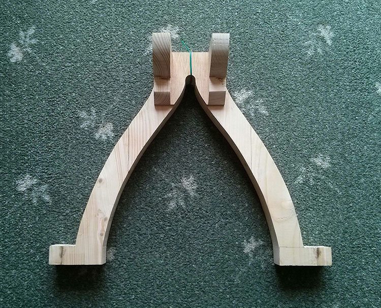
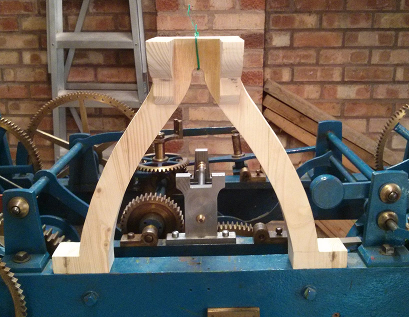
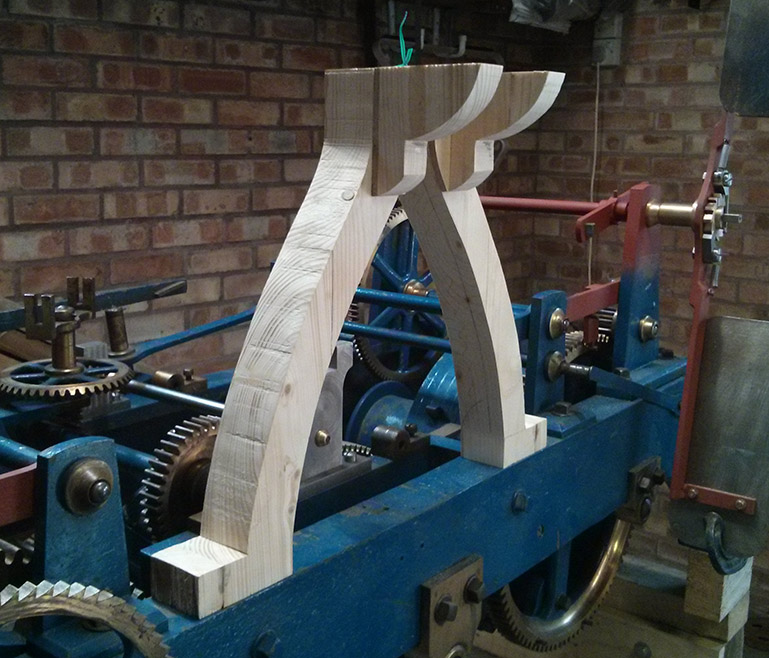
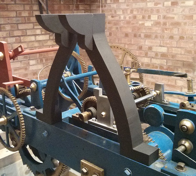
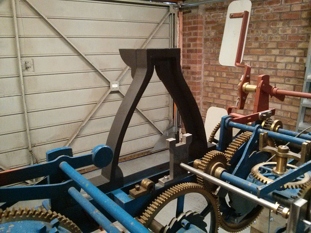
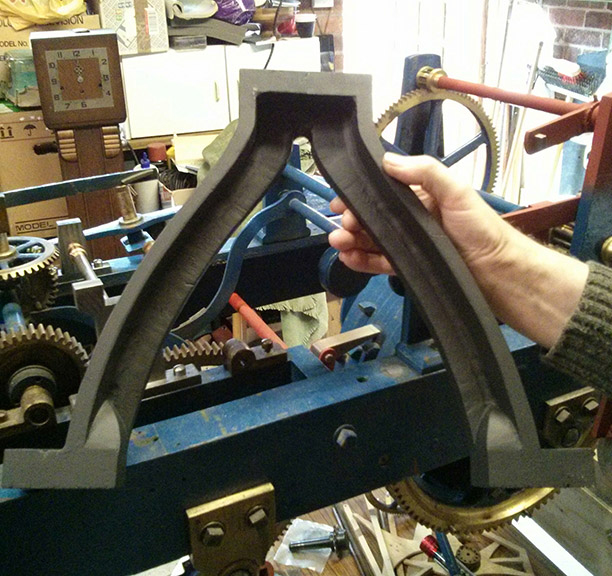
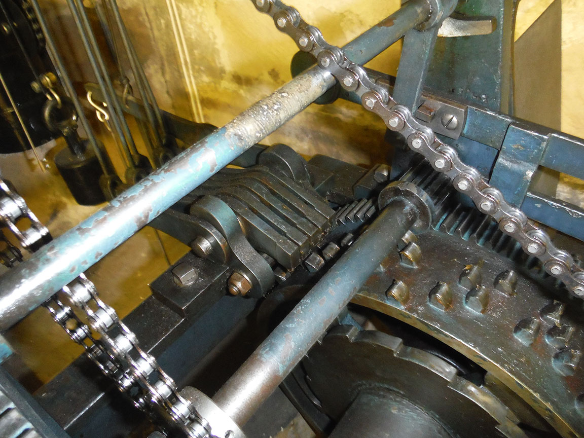
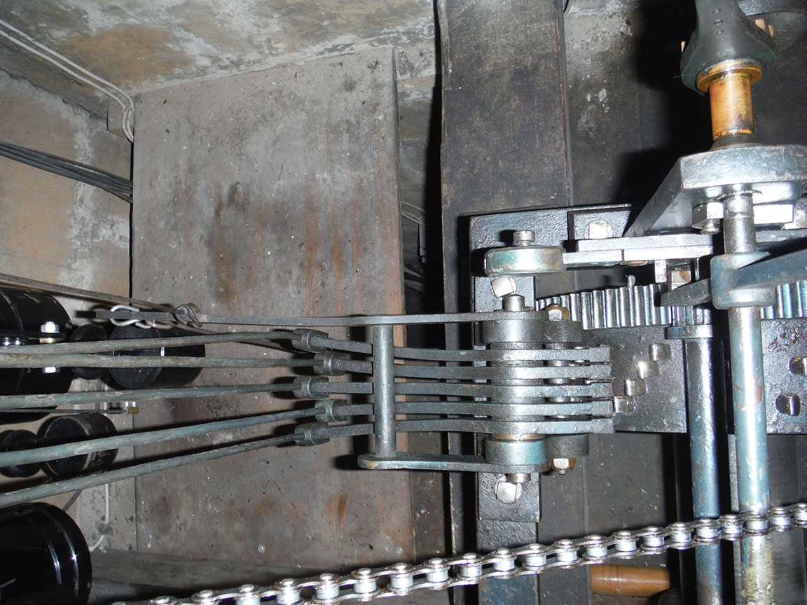
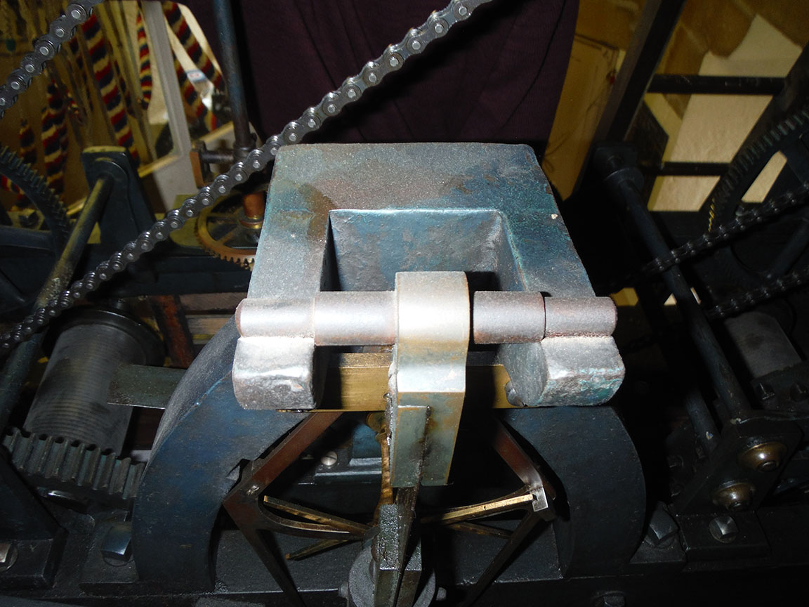
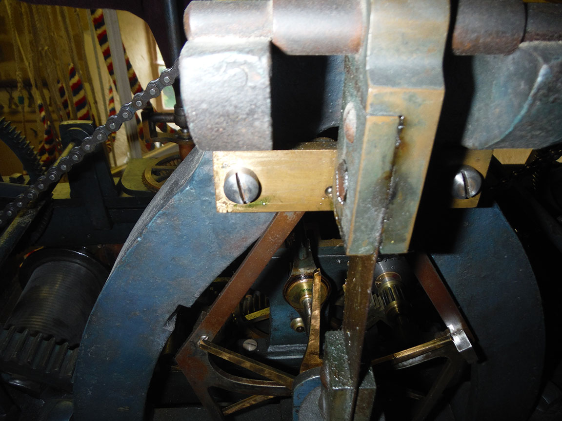
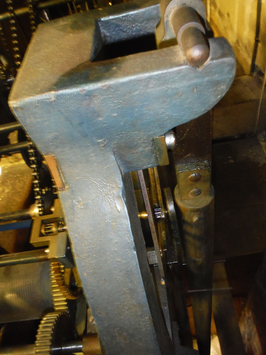
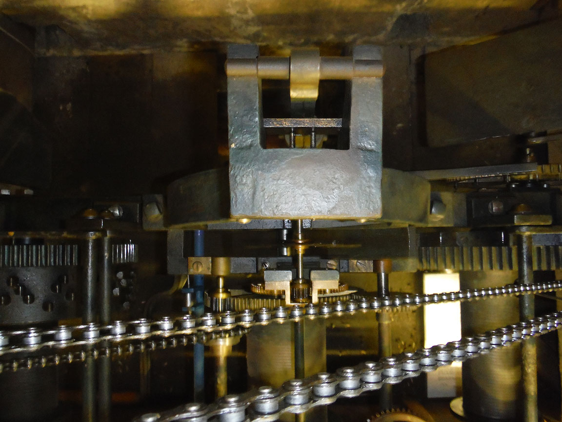
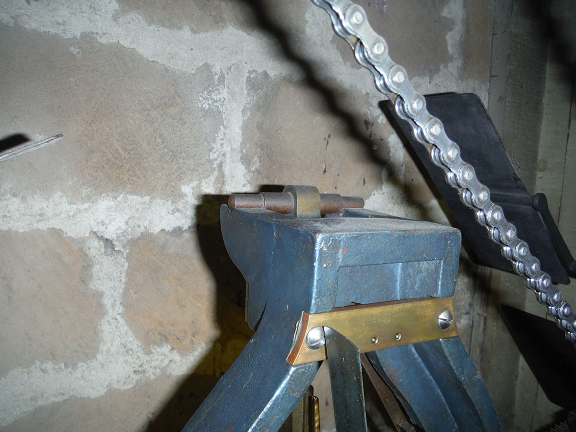
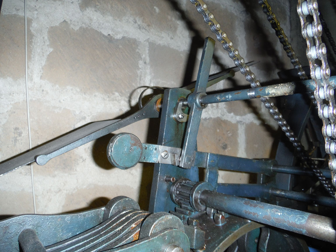
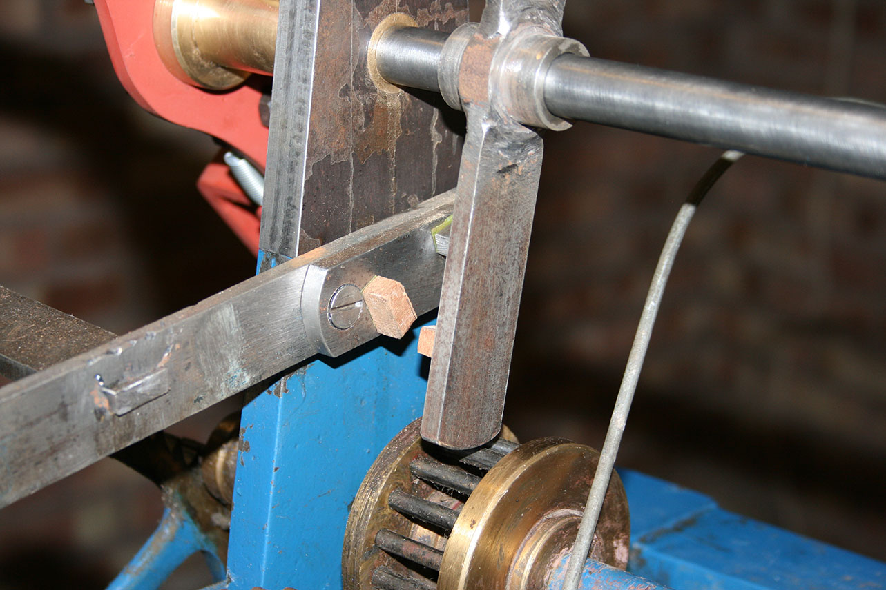
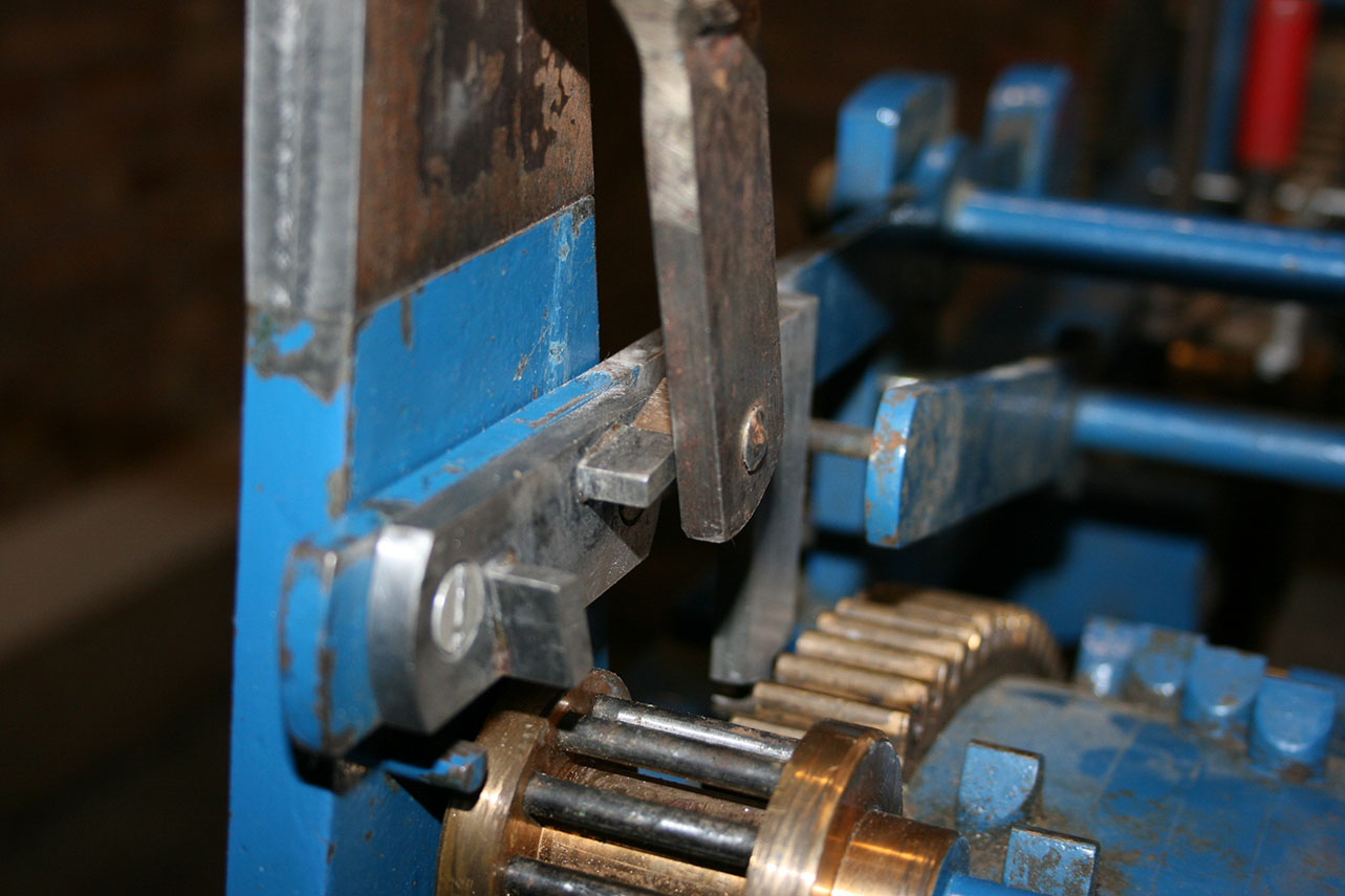
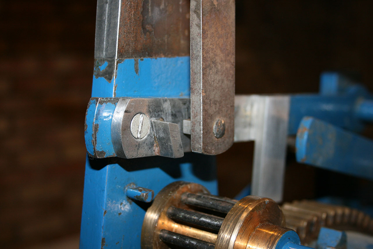
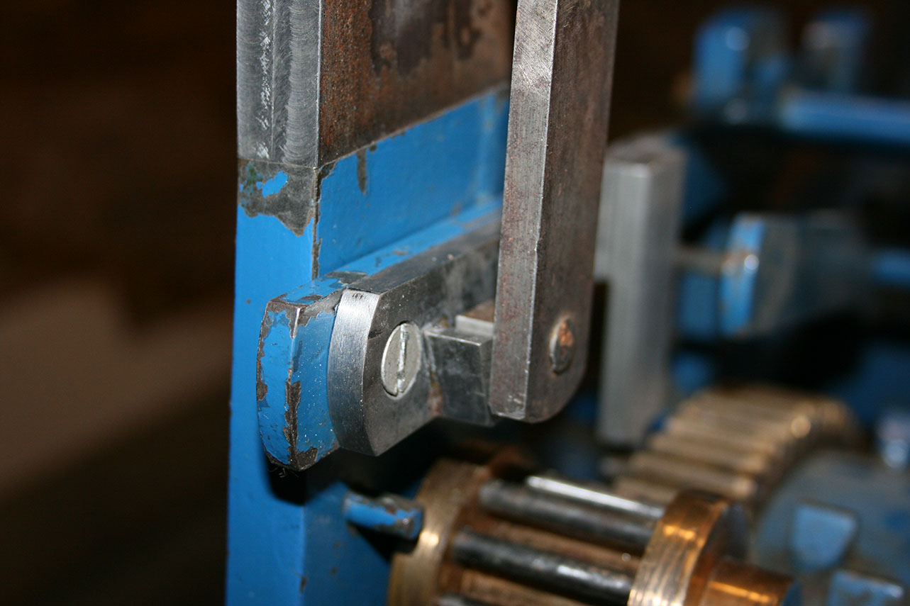
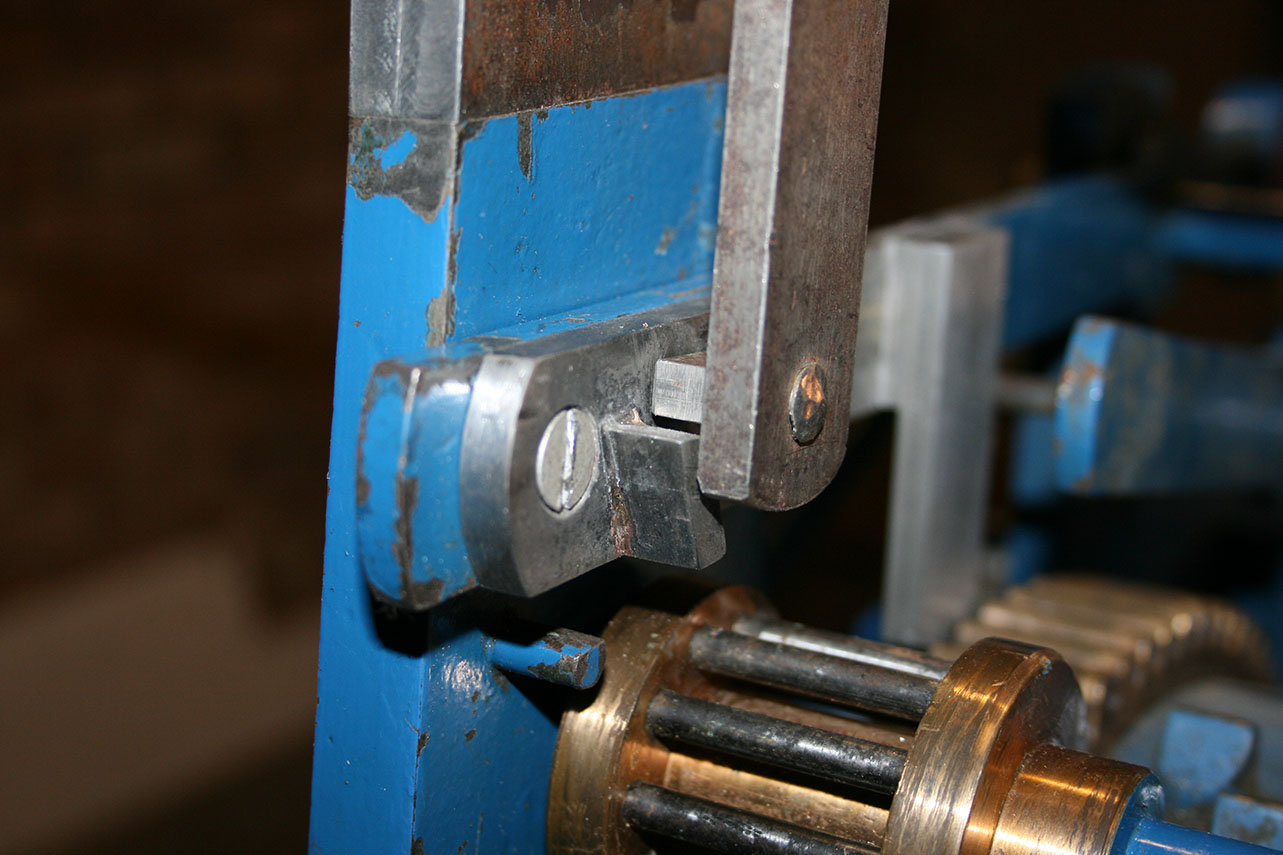
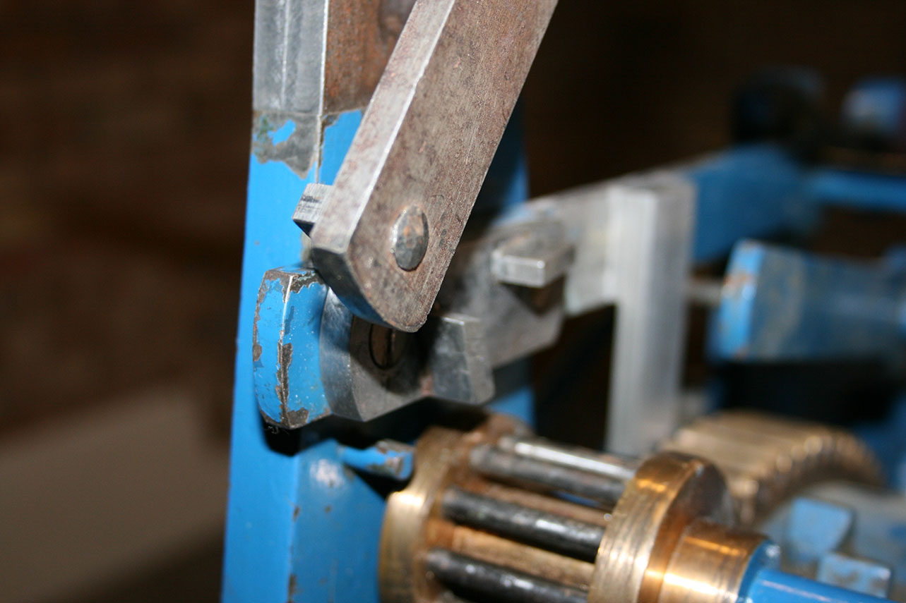
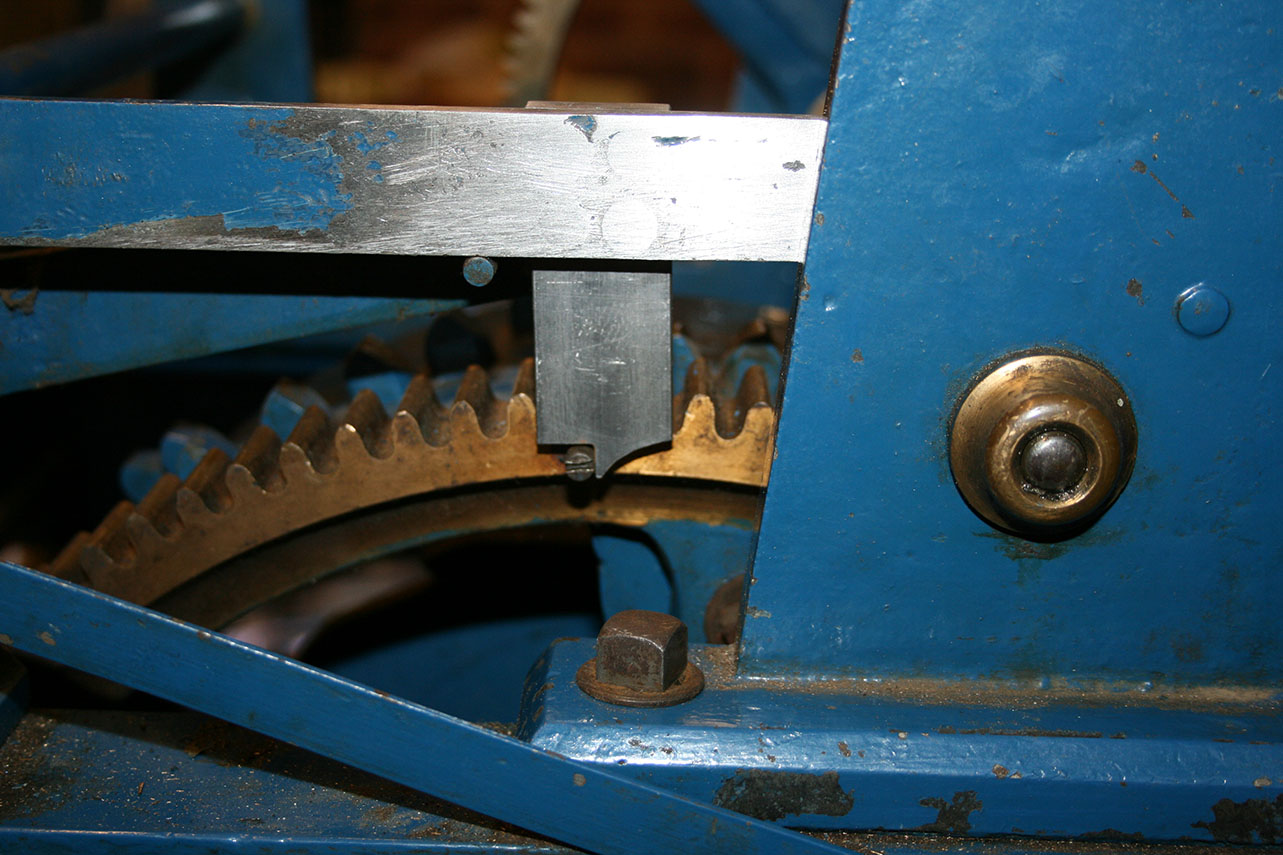
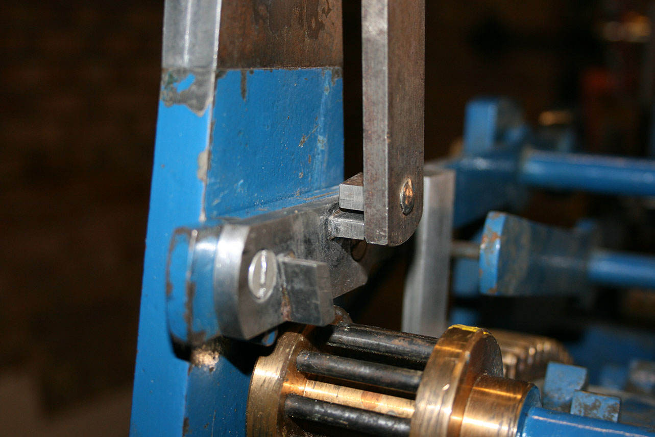
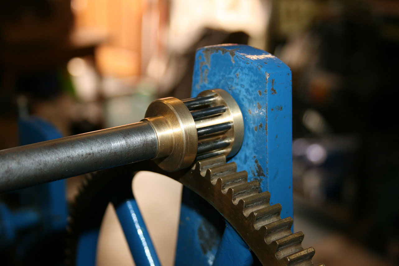
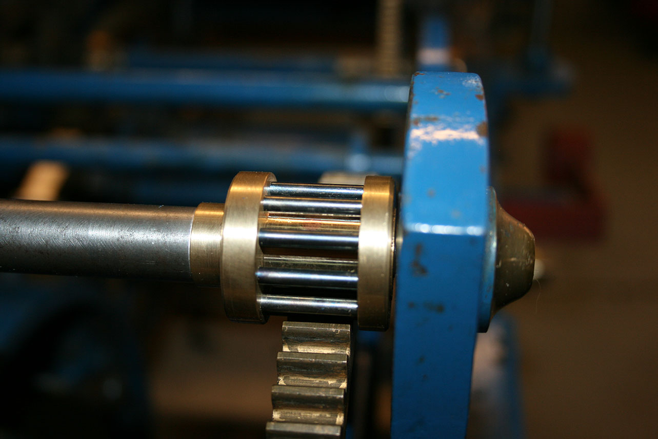
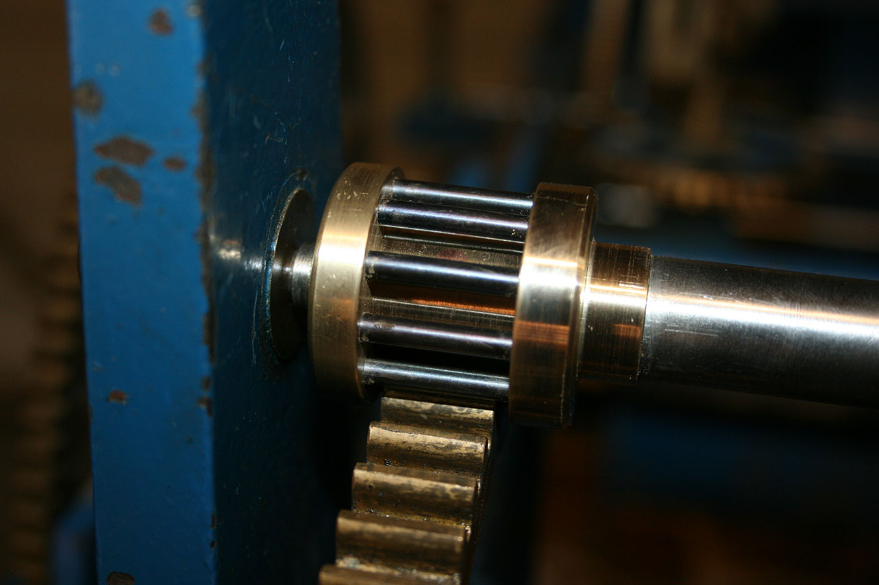
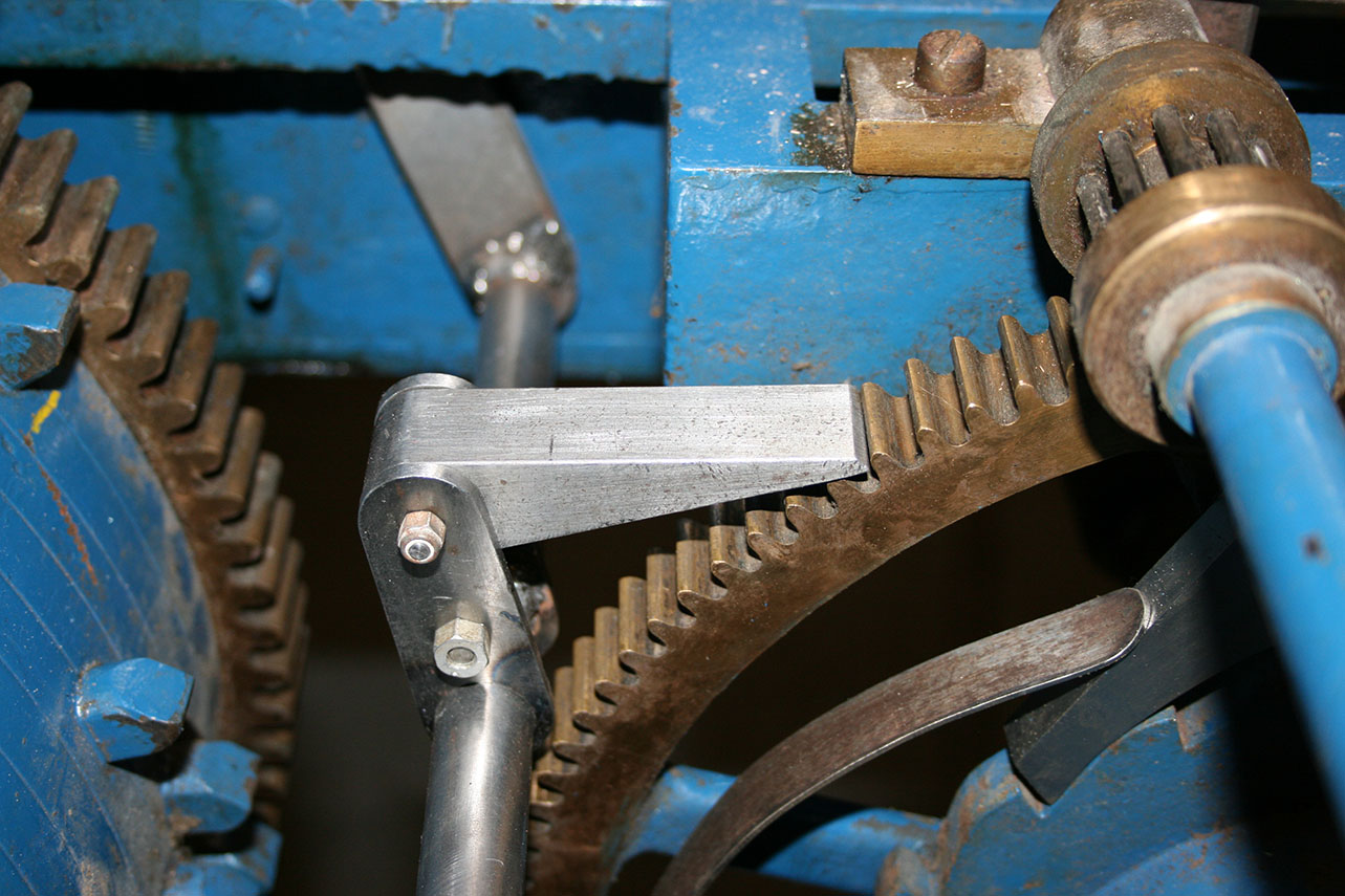
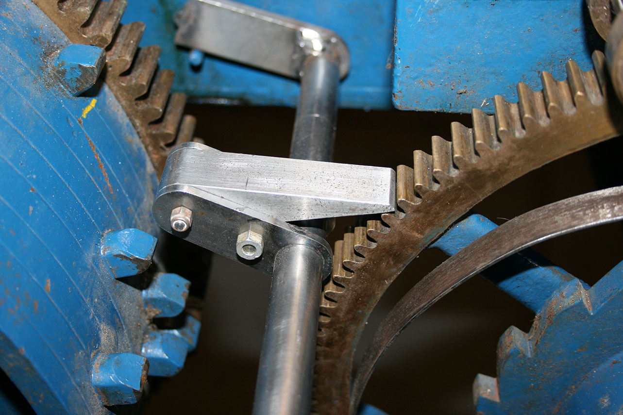
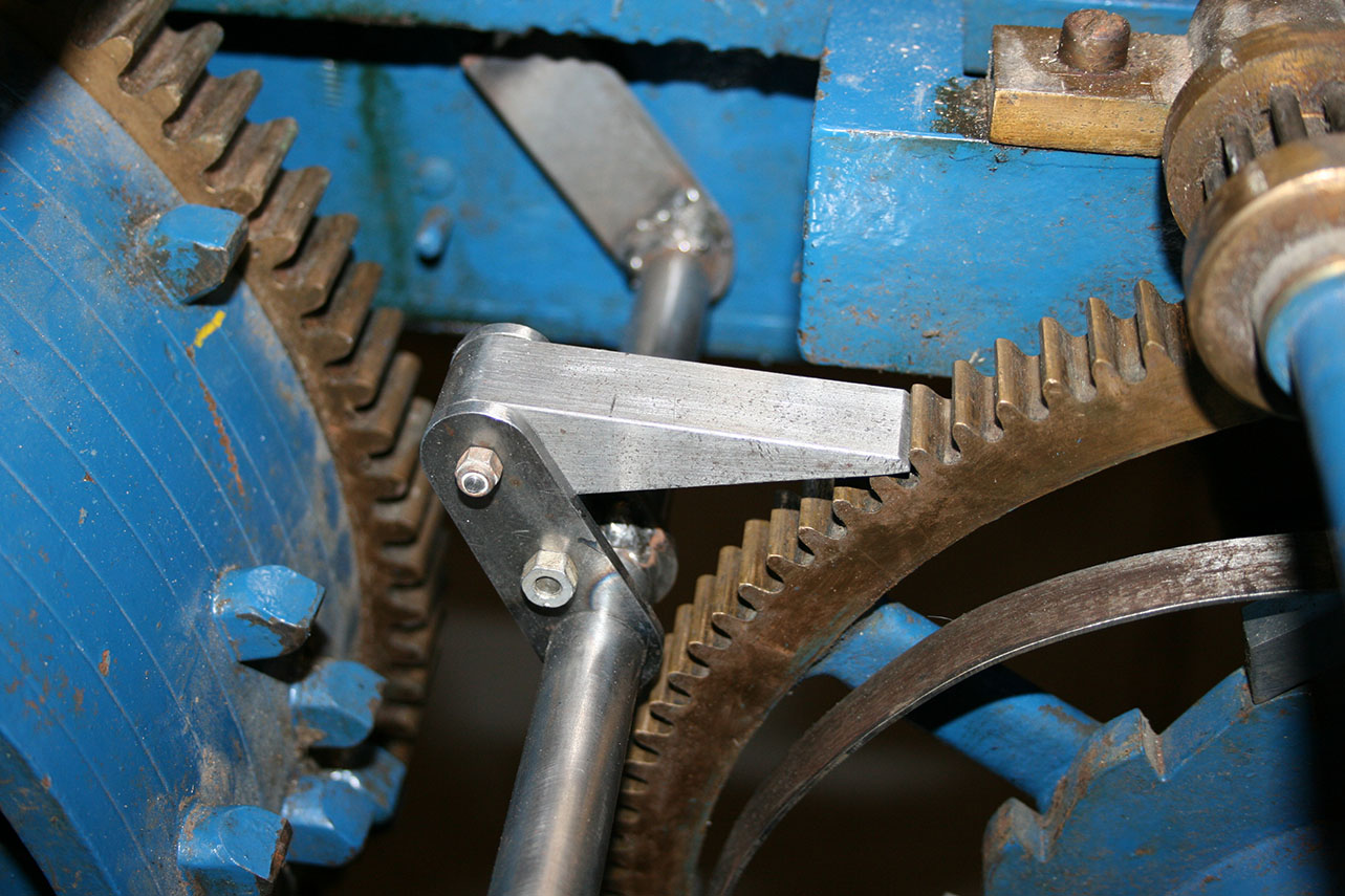
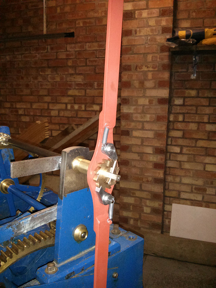
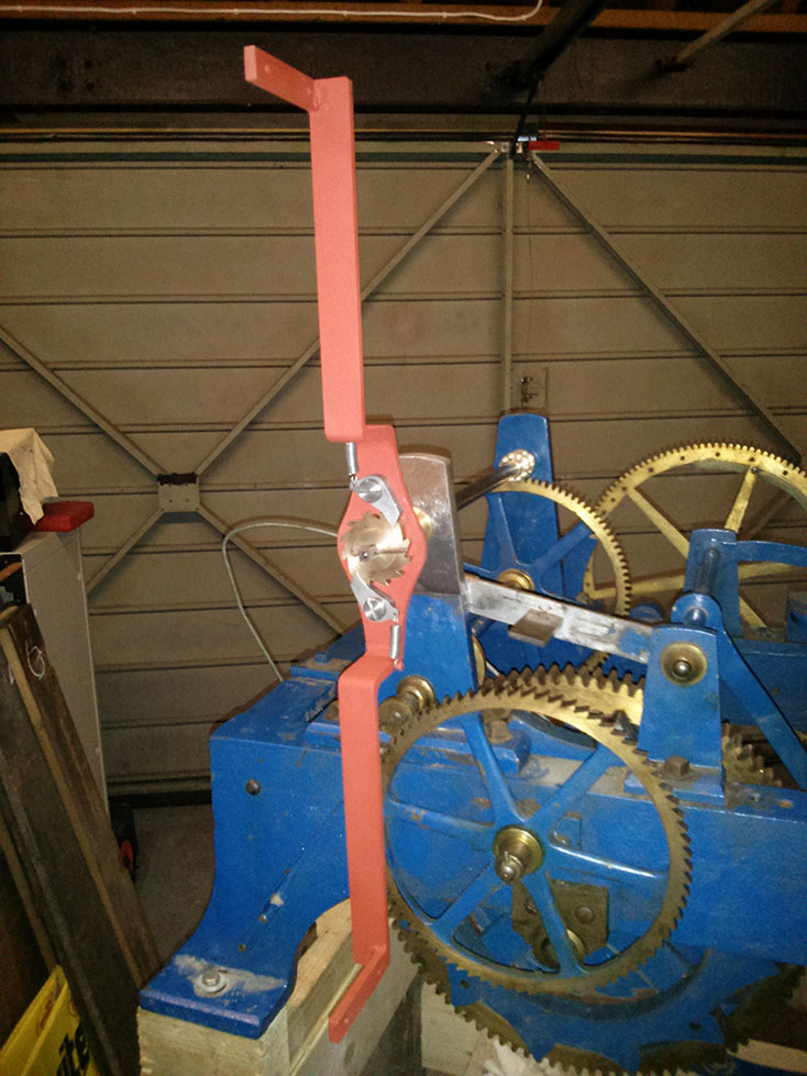
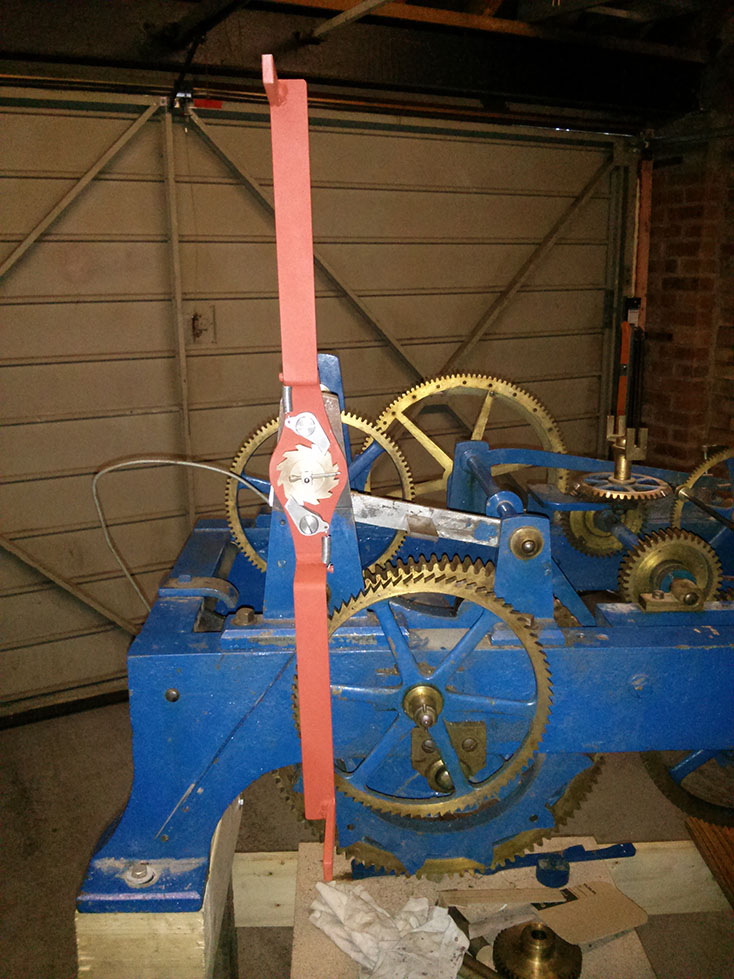
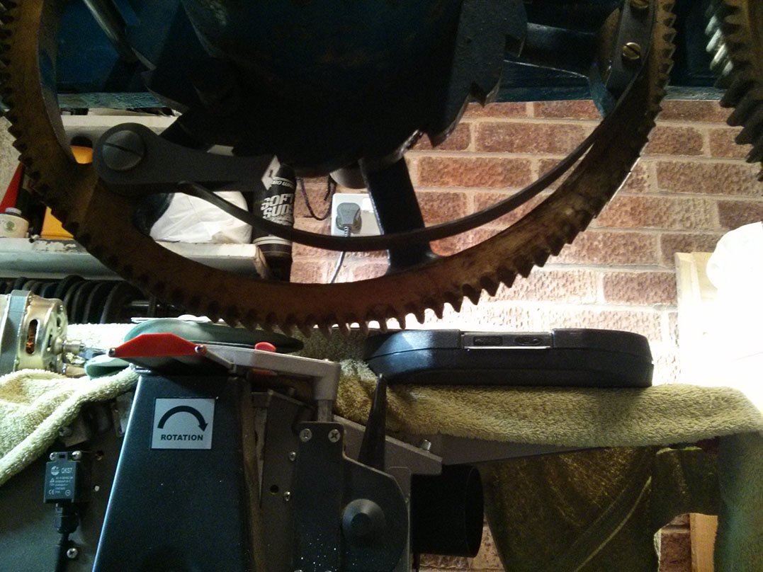
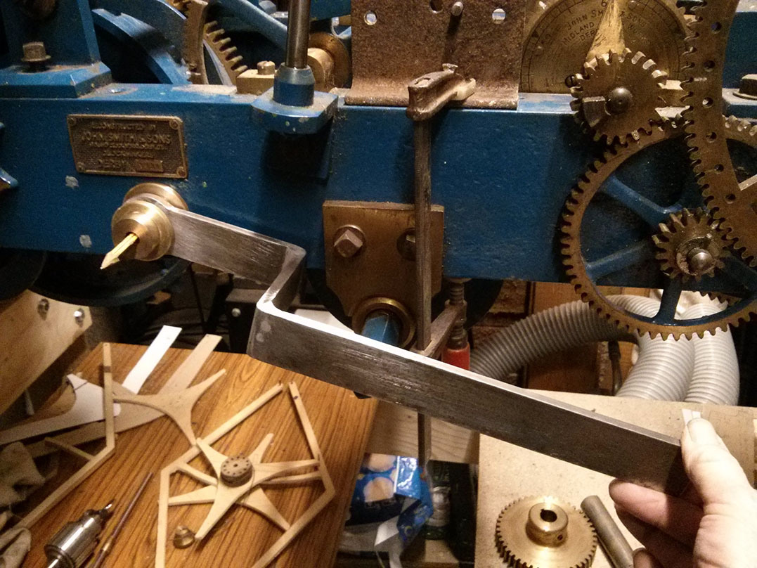
When the clock was converted to electric drive it was became little more than a gear train from the motor to the drive shaft. It no longer used a pendulum or escapement and unfortunately these were not kept with the clock. The pendulum would have been mounted on a large cast iron wishbone-shaped casting at the back of the clock. The arms of the escapement were also attached to this structure.

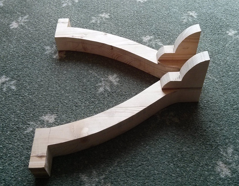
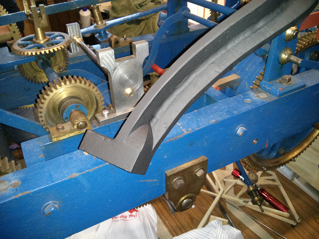
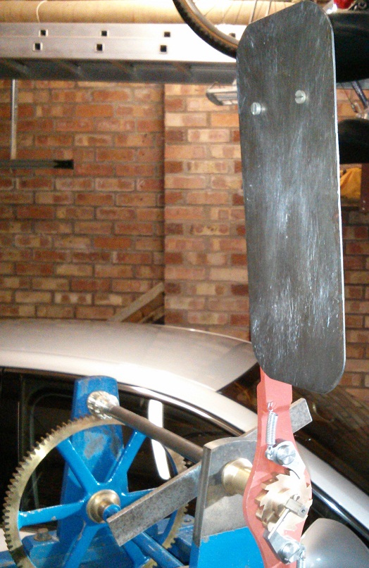
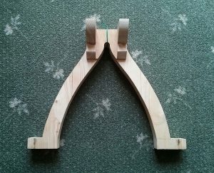
The pattern for the casting was made out of a couple of chunks of pine joined together. The basic shape was cut out with a band-saw. A small amount of hand carving was required for fine details and wax fillets were applied to the recessed front edge. Dimensions for the arch were taken from the clock of St. Alkmund’s Church, Duffield. The measurements were taken in situ, from the top of a ladder, while the clock was going. As a result they may not be quite 100% accurate, but very close to the original.

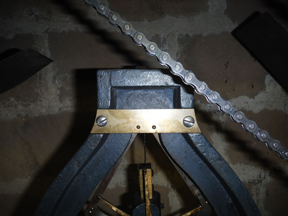
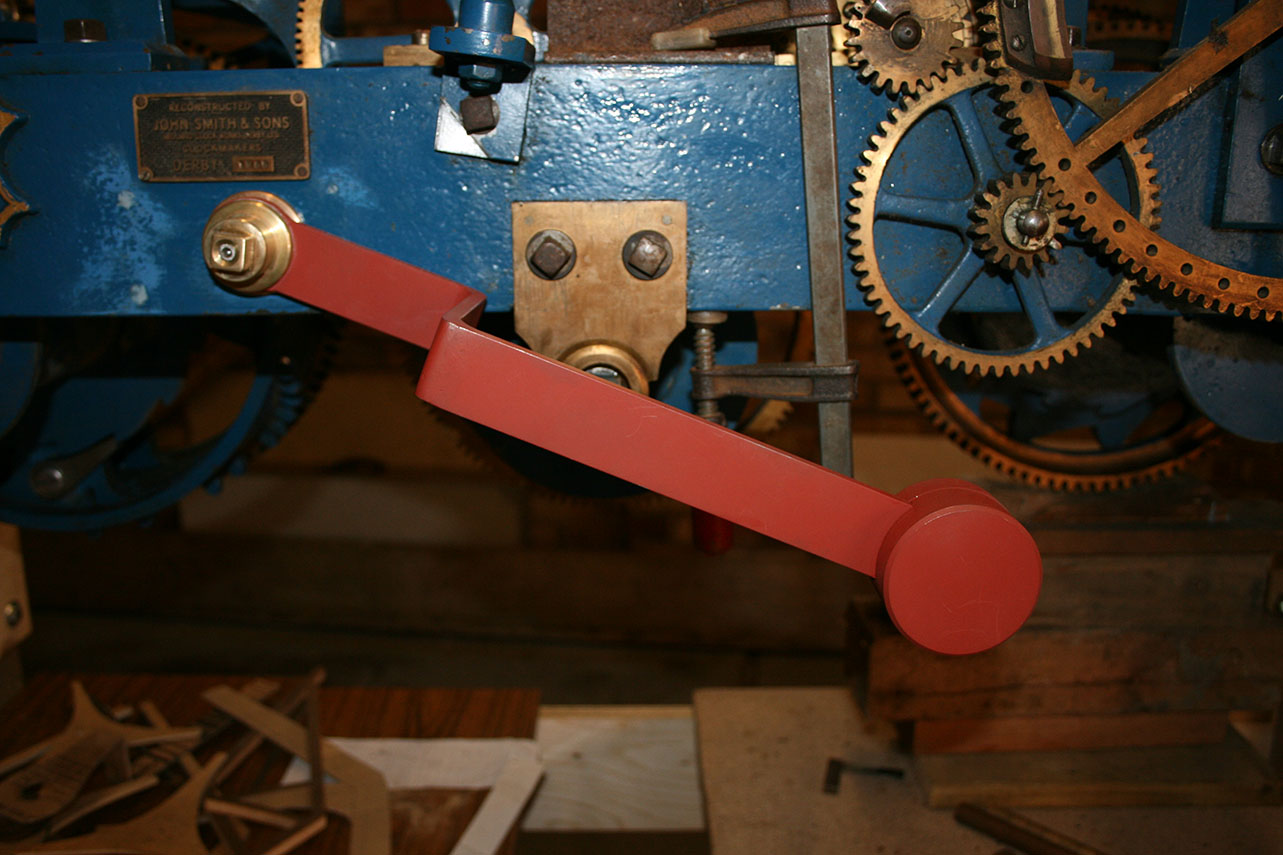
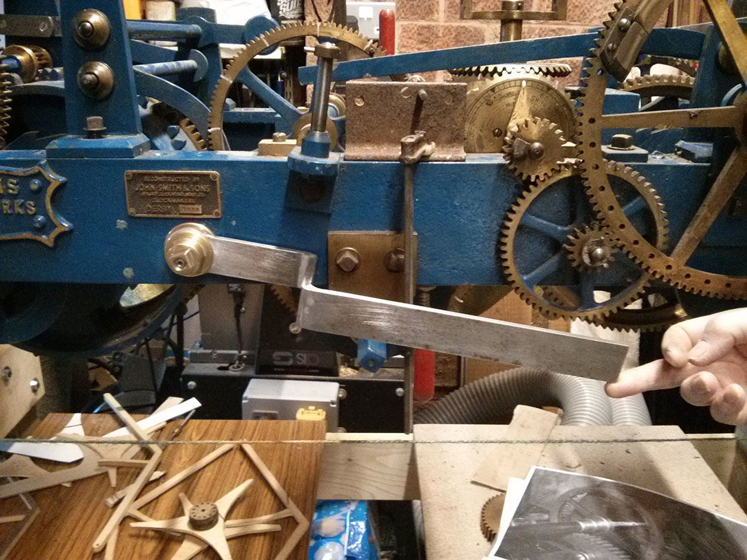
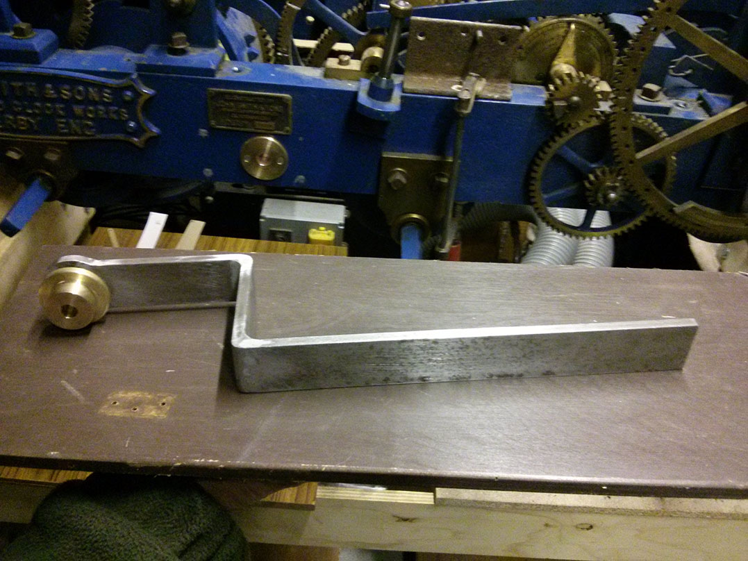
My father approached a couple of local foundries about casting the pattern. I was surprised there were any local foundries left, let alone a choice, but then Derbyshire was the birthplace of the industrial revolution! Neither of us really knew how much it was likely to cost but we were disappointed with the first quote of over £160. In the end we managed to get it for £55, with a 3 week turnaround. We’re still waiting and I’ll post pictures once we get the finished article. It’s going to need a little machining to complete. The base needs to be made flat and a v-shaped groove cut across the top for the pendulum to sit in. It also needs to accommodate two brass plates, one on the front and one on the back, to mount the arms of the escapement.

Going train revisited

Diagram of the going train

After examining the St. Alkmund’s clock we are able to start making some progress again. However, as the going train isn’t exactly the same as ours, we still don’t have all the information we need. Some details still need to be worked out. It’s also worth noting that even if it had had the same as the parts that we currently have, there is no guarantee that our missing parts would have matched – the engineer at Smith of Derby said there was a lot of variation between clocks. We may never know exactly what the original train was on this clock, so we will have to go with something sensible.

Yesterday, my father discovered something interesting we had never noticed before. The missing front arbour support, for the missing arbour, was attached to the frame by two bolts. The same support on the clock at St. Alkmund’s is attached by one bolt. That may not sound very important, and it’s possible we are reading too much into it, but of all the pictures of Smith flat bed turret clocks of this vintage we can find there is only one other that has two bolts for this support. The other is the clock at Trinity Collage, Cambridge. That clock has an extra dial at the end of this arbour and a second hand – something else the Smith engineer mentioned our clock could/ should have had. It is the presence and position of the extra dial that requires the two side bolts for fixing the support, rather than a single bolt through a front “foot”. (I’ve previously mentioned how similar I though our clock was to the Trinity clock (except for their unique fourth train) and I did contact the keeper for more details about the clock, but unfortunately never received a reply.)

So, if we assume from this observation that our clock had a second hand then that fixes the rotation speed of the missing arbour to one rpm. As the lantern pinion at the front end of this arbour must turn the 120 tooth wheel at a rate of one tooth every seven and a half seconds then that pinion must have eight trundles. Suddenly we have two less unknowns in the train!

I previously suggested some options for the missing parts of the train, but if we take the above (60 second rotation, 8 pin pinion) as correct we can improve the list of options:

  • 1.5 second swing, 60:9 ratio at escapement.
  • 1.25 second swing, 72:9 ratio at escapement.
  • 1.125 second swing, 80:9 ratio at escapement.
  • 1 second swing, 90:9 ratio at escapement.

The engineer at Smith’s did suggest a 90:9 ratio, but I find it hard to imagine this clock only had a one second pendulum. That’s only about a metre, the same as a typical long case (“grandfather”) clock. The pendulum at St. Alkmund’s is 1.5 seconds or about 2.24m. The Trinity clock pendulum is described as being “2 metres” but it’s not clear how they are measuring it. The length of a pendulum is measured from the pivot to the centre of mass and so the overall physical length of the pendulum may be quite a bit longer. 2m is not a standard/ common length so I suspect it’s an approximation of the physical length rather than an accurate “functional length”.

As we’ll never know what this clock originally had we can choose one of the above options, keeping in mind the practicalities of the pendulum length. Only the 1 second pendulum would fit the clock on its current stand and would be the most convenient length, but that feels too short to me. The 1.5 second pendulum is far too long to be practical, so our current intention is to make it with a 1.25 second pendulum and 72:9 ratio. We just need to make sure that actually fits around the rest of the escapement mechanism.

Clock of St Alkmund’s Church, Duffield

St. Alkumund's Church, Duffield, Smith of Derby turret clock

Unfortunately here has been little progress on our clock over the summer as we have been stuck on the escapement. However, we have finally managed to track down a suitable clock for us to model our missing escapement on. The clock is of course a J Smith & Sons, Derby and is of pretty much the same size and design as our own. In the end we didn’t have to go far to find it either, about 5 miles from my house is St Alkmund’s Church, Duffield. Where, coincidentally (or probably not), I will be getting married next year. I must thank Mike Banks (previous clock keeper), Luke Heaton (tower captain) & James Buchanan (assistant minister) for making this visit possible.

The clock is slightly older than ours at 1897 (vs. 1922), and there are a number of differences, but many of the important details are the same.

Some differences:

  • The going train is geared differently, unfortunately I can’t say exactly what it is because it’s very difficult to count teeth on a working clock, up a ladder, without touching it or putting chalk marks on it.
  • The going train winding arbour passes through the frame rather than being mounted under it (the other two trains are mounted under, as are all three on our clock). This seems to be the norm on these slightly older models.
  • The larger lantern pinions on our clock are more like regular pinions (but with closed ends) on this clock.
  • It has a five bell chime, ours has eight (although, unlike us, St Alkmund’s actually have the bells to go with it, in fact they have an impressive ten bells in total).

Now we have measurements for lots of details we didn’t before, as well as having actually seen one up close (which makes a big difference). We are now in the process of drawing up the missing parts and planning the next steps of our restoration.

Here are some pictures of various parts of the clock we wanted a closer look at.

The slightly different striking control

Strike control mechanism - lifting projection

We assumed the striking and chiming control mechanisms were the same, however we found a subtle but important difference. At first we were unable to get the mechanism to run correctly. It just didn’t work from any obvious starting point of the two pin pinion.

The significance of the two pin pinion is that the ratchet wheel does not move in a continuous manner but rather in steps (two per revolution of the arbour). The equivalent wheel on the chiming train moves continuously.

This is important because the ratchet wheel, which contains the lifting pin, must move at the start of the striking process (to allow the horizontal arm to drop) and at the end (to lift the arm back up). For the striking train it moves one step per hour being struck. Considering the striking of one o’clock, where the ratchet wheel only moves one tooth, it is clear that there must be movement of half a tooth at the start and half a tooth at the end of striking. That means the rest position of the ratchet wheel must be mid-movement, so the spring pawl cannot sit in a fully engaged position at rest, it needs to sit half way between teeth. This doesn’t seem like a natural resting position, but it does work. When at rest one of the pins is engaged with the ratchet wheel and when the pin comes out of mesh the pawl is engaged. The result is that either a pin or the pawl is always engaged with the ratchet wheel to prevent it moving inappropriately.

The fly arbour rotates five times per tooth of the ratchet wheel / strike of the bell.

To strike one o’clock:

  • The first rotation of the fly arbour moves the ratchet wheel half a tooth, the two pin pinion disengages from the ratchet wheel and the spring pawl engages. This movement is enough for the horizontal arm to drop off the lifting pin on the ratchet wheel.
  • The fly arbour then rotates freely for four turns, the two pin pinion remains out of mesh with the ratchet wheel.
  • In the final half rotation the second pin in the pinion engages with the ratchet wheel and moves it half a turn. This causes the lifting pin to raise the horizontal arm and stop the striking mechanism.
  • The rest of the mechanism works just like the chiming mechanism.

The lifting projection has to be very slim so it isn’t able to accommodate much of a ramp – the pictured projection doesn’t look like it would work but it does, in fact it works very well. Note the pictures showing the resting positions of the ratchet wheel, pawl and two pin pinion. There is also a picture showing how the positions of the blocks were prototyped in wood (attached with double sided tape).

Completed chime control mechanism

Finished chime control mechanism

The control mechanism for the chiming train is now complete (all but for pinning the rotating arm to the fly arbour). Read the previous two posts on this mechanism for background.

I’ll repeat the explanation (improved and modified slightly) from the earlier post of how the process works, with pictures of the finished product.

Starting position before chiming

Chime control mechanism - raised on stopping pin

The horizontal arm is held just above the rest pin. It is held there by the downward projection from the arm which has been lifted onto one of the four pins around the large wheel attached to the barrel.

Chime control mechanism - locked position

The rotating arm on the fly arbour is always trying to rotate clockwise but is obstructed because the square block projecting from it is locked against the square block projecting from the catch plate. Note the horizontal arm is above the rest pin.

Chiming process

Chime control mechanism - first stage of unlocking

The horizontal arm is lifted (note the increased gap between the rest pin and the arm) briefly by the going train, on each quarter hour. This unlocks the rotating arm, attached to the fly arbour so its projecting block can pass below the block on the catch plate.

Chime control mechanism - temporary locking stage

The projecting block of the rotating arm now briefly locks against the upright (angled) block on the catch plate, awaiting its final release.

Chime control mechanism - final release

The lifting mechanism from the going train disengages, causing the horizontal arm to drop back to it’s starting position (still above the rest pin). This unlocks the rotating arm again and allows the projecting block on the arm to pass over the upright block.

Chime control mechanism - starting to rotate

The fly arbour begins to rotate, which means the rest of the striking train moves too.

Chime control mechanism - off the lifting pin

About half way through the first rotation of the fly arbour the large wheel on the barrel has rotated far enough that the downward projection from the horizontal arm drops off the pin.

Chime control mechanism - rotating freely

The horizontal arm drops down, below it’s starting point, and finally rests on the rest pin. This allows the rotating arm to rotate freely, it’s projecting block passing over the horizontal block on the catch plate.

Chime control mechanism - raised on stopping pin

When the chime barrel reaches the end of the tune, the next pin on the wheel reaches the point where it raises the horizontal arm.

Chime control mechanism - locked position

The block on the rotating arm now collides with the horizontal block on the catch plate causing the arbour, and rest of the train, to stop abruptly (except the fly, which is able to come to  rest gradually thanks to its ratchet drive).

Completed fly arbour pinions

Completed fly arbour lantern  pinion, angled view

The completion of the flies meant the lantern pinions could be attached to the fly arbours. They are now pinned though the centre section, just like the originals, and the pins have been machined perfectly smooth with the pinion body.

The pins have been cut to length and hardened. Then the brass end cap was attached – a simple tight push fit. The end cap has then been machined to a perfect match with the body and a little bevel put on, which helps to mask any visible line at the join.

Compare the pictures of the two new pinions with one of the originals when I originally discussed their construction. Note the bronze dot just visible between the trundles where it is pinned to the arbour.


Completed maintaining power

Maintaining power pawl, riding over teeth of great wheel.

The maintaining power is now completely finished. The lever has a weight. The pawl to advance the great wheel has been made and attached (welded to the arbour). There is even a stop to prevent the lever being lifted too high and to prevent it dropping below the level of the winding peg.

From the fully charged position (lever all the way up) there is approximately four minutes to wind the going train. It actually takes about six minutes to return to resting position but because it passes in front of the winding peg it would rest on the winding handle if it were still attached beyond four minutes. Passing in front of the winding peg is deliberate, it means you have to charge it before you are able to wind the going train. You don’t want a turret clock slowing down on you else you employees might be late for work!

As we currently have no weights to wind up we have no idea how long winding will take. Luckily if it takes more than the time allowed the maintaining power can be recharged mid-wind as many times as needed.

The pictures show the pawl in three positions, from fully charged to resting gently on the teeth of the great wheel as it rotates beneath it (which it always does when not charged).

Completed fly

IMG_20150222_135813

The flies now have arms and are essentially complete. The exact sizes are estimates, based on clocks seen in person and online. It may be that some tweaking of the paddles is needed further down the line to correctly control the striking. We would still like to see more turret clocks in person to make this kind of educated guesswork more accurate.

Due to the position of other components on the outside of the frame the striking fly has a crank in it. The chiming fly only needed a 1/4 inch offset to give sufficient clearance. It is normal for the two flies to be different, they aren’t both made cranked just for the sake of matching.

The arms are made from 1/4 inch steel, welded together rather than a single piece (otherwise quite a large, but narrow, plate would have been needed). The blades of the fly are made from approx 0.064 inch thick steel. Pawls have been made to engage with the previously made ratchet, with springs attached to the arms.

The arms have been sprayed in red oxide to prevent corrosion, this is not the intended final colour. We do plan to fully repaint the clock once complete but the final colour hasn’t been decided yet. Current thinking is a dark green (in which case probably British Racing Green). We don’t know what the original colour would have been, quite possibly the same blue as it came but that’s not certain.

Barrel ratchet pawl & spring

IMG_20150205_122430

It’s been pretty cold again here so progress had been limited for the last couple of weeks, but another small job has been completed. All three of the barrel ratchet pawls were missing from the clock, along with their springs, and the pin to attach the pawl on the going train (the pins on the other trains did more than just hold the pawl so had been left on). When the clock was directly motor driven theses were no longer needed.

Replacement parts had to be made. The springs are riveted to a small block that bolts to two threaded holes on the wheel (3BA thread), as you can see in the pictures.

When purchased the barrel and the wheel were stuck together, I was worried they might have done something nasty to join them. However,  with dismantling and cleaning, they have freed off and now work nicely as they should.

Maintaining power

IMG_20150131_163813

The maintaining power is a device for keeping the clock going while you wind it (and winding a turret clock can take a while). The type on this clock involves a weighted lever which must be lifted to allow the winding handle to be attached. Lifting the lever engages a pawl with the great wheel to apply force to the going train. The lever slowly returns to its resting position as the clock continues, by which time the winding should be finished.

The hole at the front of the clock for the maintaining power arbour had been covered by a John Smith & Sons, Derby plaque, which was our only clue to the fact that Smith’s had done the conversion. Smith’s confirmed this was how it used to be done when my Father visited them.

You can see in the pictures some liquid weld filling three of the bolt holes where the plaque was removed (the head sheared off the fourth). They look a bit ugly now but once they’re smoothed down and the clock is repainted you’ll never know there’d been a plaque there.

A new blush was made for the front and there isn’t one at the back (the arbour goes straight into a hole in the frame). There isn’t a great deal of movement here, but without a removable bush at at least one end there would be no way to get the arbour in and out.

Then a cranked lever is attached to the squared off arbour and a fancy brass nut holds it all in place.

Next steps are the pawl, the weight on the end of the lever and a stop to prevent the lever going down too far.